


10 - 5
10. CHARACTERISTICS
(2) Heat dissipation area for enclosed servo amplifier
The enclosed control box (hereafter called the control box) which will contain the servo amplifier should be
designed to ensure that its temperature rise is within
10 at the ambient temperature of 40 . (With a 5
(41
) safety margin, the system should operate within a maximum 55 (131 ) limit.) The necessary
enclosure heat dissipation area can be calculated by Equation 10.1.
P
A
KT
............................................................................................................................................. (10.1)
where, A : Heat dissipation area [m
2
]
P : Loss generated in the control box [W]
T : Difference between internal and ambient temperatures [ ]
K : Heat dissipation coefficient [5 to 6]
When calculating the heat dissipation area with Equation 10.1, assume that P is the sum of all losses
generated in the enclosure. Refer to Table 10.1 for heat generated by the servo amplifier. "A" indicates the
effective area for heat dissipation, but if the enclosure is directly installed on an insulated wall, that extra
amount must be added to the enclosure's surface area.
The required heat dissipation area will vary wit the conditions in the enclosure. If convection in the
enclosure is poor and heat builds up, effective heat dissipation will not be possible. Therefore, arrangement
of the equipment in the enclosure and the use of a cooling fan should be considered.
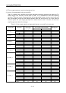
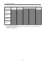
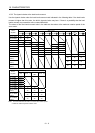
Table 10.1 lists the enclosure dissipation area for each servo amplifier when the servo amplifier is operated
at the ambient temperature of 40
(104 ) under rated load.
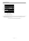
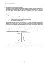
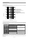
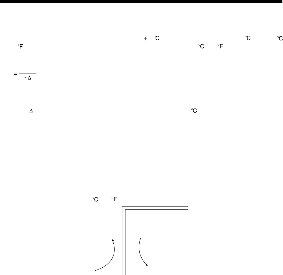
(Outside)
(Inside)
Air flow
Fig. 10.2 Temperature distribution in enclosure
When air flows along the outer wall of the enclosure, effective heat exchange will be possible, because the
temperature slope inside and outside the enclosure will be steeper.