


13 - 79
13. SERVO AMPLIFIERS WITH A LARGE CAPACITY (30k TO 55kW)
13.9.3 External dynamic brake
POINT
Configure up a sequence which switches off the contact of the brake unit after
(or as soon as) it has turned off the servo on (signal) at a power failure or
failure.
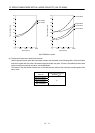
For the braking time taken when the dynamic brake is operated, refer to
section 13.8.3.
The brake unit is rated for a short duration. Do not use it for high duty.
The specifications of the input power supply for external dynamic brake are
the same as those of the converter unit control circuit power supply.
Operation timing is the same as that for servo amplifiers with 22kW or less.
Refer to section 11.6.
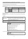
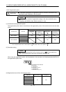
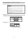
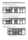
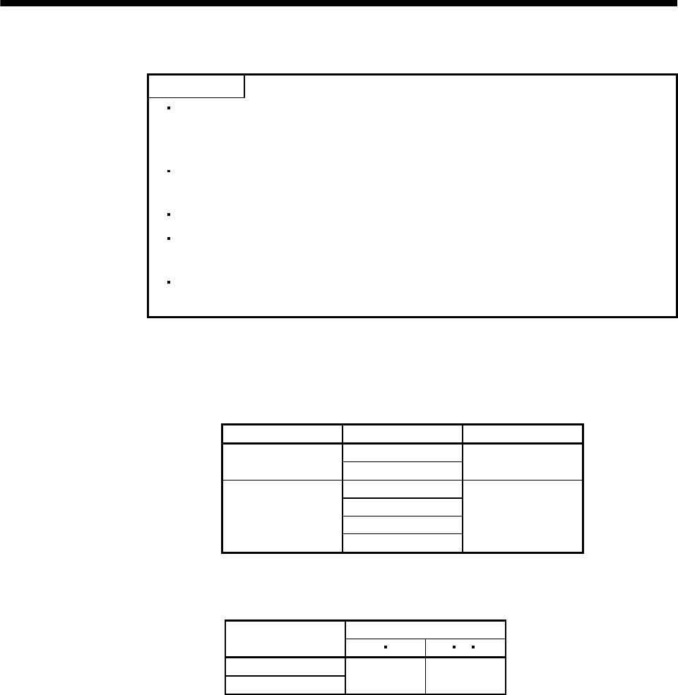
(1) Selection of dynamic brake
The dynamic brake is designed to bring the servo motor to a sudden stop when a power failure occurs or
the protective circuit is activated. When using the external dynamic brake, assign the dynamic brake
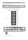
interlock (DB) to any of CN3-9, CN3-13, and CN3-15 pins in parameter No.PD07 to PD09.
Converter unit Drive unit Dynamic brake
MR-J3-DU30KB
MR-J3-CR55K
MR-J3-DU37KB
DBU-37K
MR-J3-DU30KB4
MR-J3-DU37KB4
MR-J3-CR55K4
MR-J3-DU45KB4
MR-J3-DU55KB4
DBU-55K-4
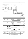
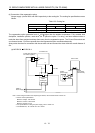
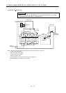
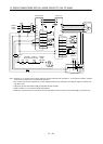
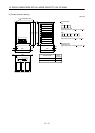
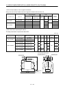
(2) Connection example
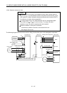
Use the following wires to connect the dynamic brake.
Wire[mm
2
] (Note) Dynamic
brake
a
b U V W
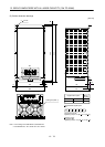
DBU-37K
DBU-55K-4
2 14
Note. Selection condition of wire size is as follows.
Wire type: 600V Polyvinyl chloride insulated wire (IV wire)
Construction condition: One wire is constructed in the air