11 - 27
11. OPTIONS AND AUXILIARY EQUIPMENT
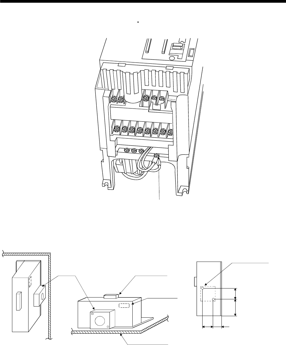
The drawing below shows the MR-J3-350B4
MR-J3-500B(4). Refer to section 9.1 (6) outline drawings
for the position of the fixing screw for MR-J3-700B(4).
Built-in regenerative resistor
lead terminal fixing screw
For the MR-RB51, MR-RB3G-4, MR-RB5G-4, MR-RB34-4 or MR-RB54-4 install the cooling fan as
shown.
(for cooling fan installation)
Depth 10 or less
(Screw hole already
machined)
Cooling fan installation screw hole dimensions
82.5
40
82.5133
2-M3 screw hole
Terminal block
Thermal relay
Installation surface
Horizontal installation
Vertical
installation
Top
Bottom
[Unit : mm]
Cooling fan


