


11 - 39
11. OPTIONS AND AUXILIARY EQUIPMENT
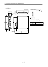
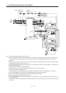
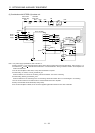
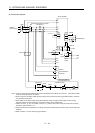
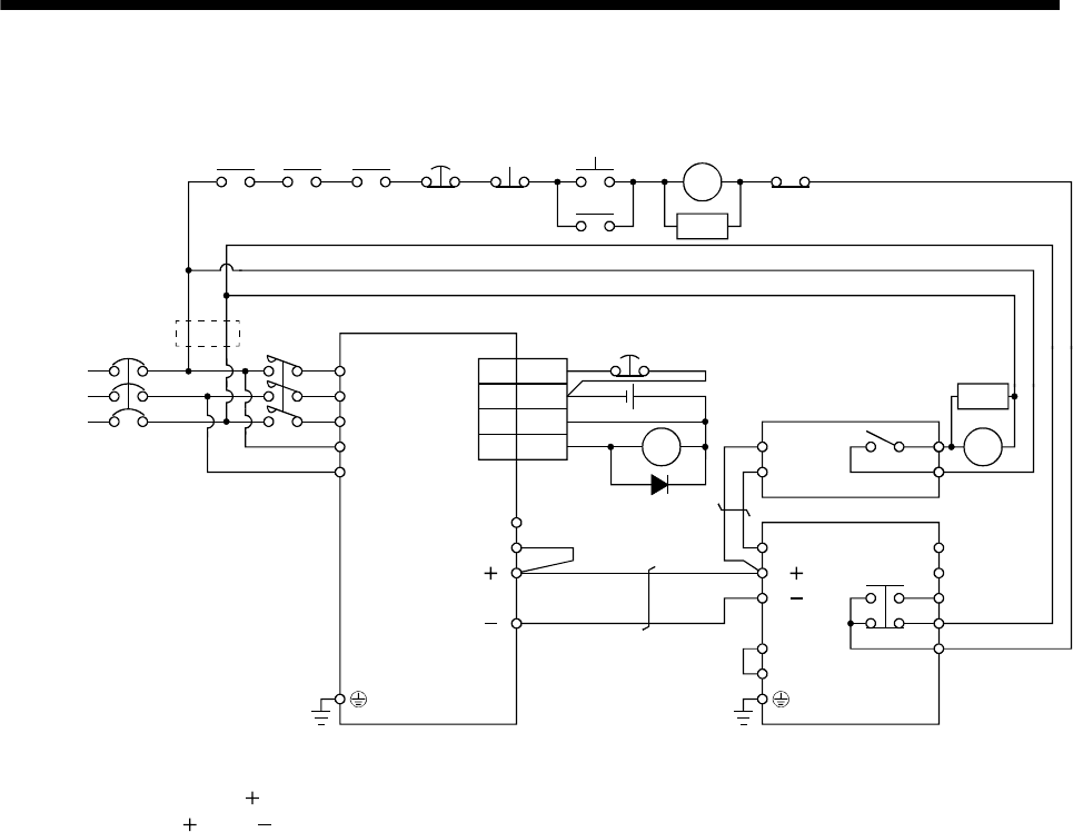
(2) Combination with MT-BR5-(H) resistor unit
NFB
24VDC
ALM
RA1
MC
SK
MC
ON
OFF
EM1
Servo motor
thermal relay
RA2
(Note 1)
Power
supply
N/
P/
BUE
SD
PR
B
C
A
SD
MSG
(Note 3)
(Note 6)
RA4
3
10
EM1
DOCOM
DICOM
ALM
P
1
P( )
N( )
FR-BU2-(H)
MT-BR5-(H)
Servo amplifier
P
PR
TH2
TH1
(Note 5)
MC
(Note 4)
RA4
(Note 7)
(Note 2)
20
15
CN3
L
3
L
11
L
2
L21
L1
SK
(Note 8)
RA1
Controller
forced stop
RA3
C
(Note 9)
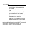
Note 1. For power supply specifications, refer to section 1.3.
2. Always connect P
1 - P( ) terminals (Factory-wired). When using the power factor improving DC reactor, refer to section 11.13.
3. Connect the P/
and N/ terminals of the brake unit to a correct destination. Wrong connection results in servo amplifier and
brake unit malfunction.
4. For the servo amplifier of 400V class, a step-down transformer is required.
5. Contact rating: 1a contact, 110VAC_5A/220VAC_3A
Normal condition: TH1-TH2 is not conducting. Abnormal condition: TH1-TH2 is conducting.
6. Contact rating: 230VAC_0.3A/30VDC_0.3A
Normal condition: B-C is conducting/A-C is not conducting. Abnormal condition: B-C is not conducting/A-C is conducting.
7. Do not connect more than one cable to each P and N terminals of the servo amplifier.
8. Always connect BUE and SD terminals (Factory-wired).
9. For the servo amplifier of 22kW, do not connect a supplied regenerative resistor to the P and C terminals.