


11 - 26
11. OPTIONS AND AUXILIARY EQUIPMENT
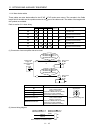
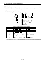
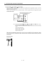
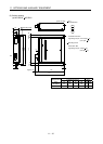
(b) MR-J3-350B4
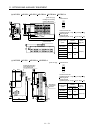
MR-J3-500B(4) MR-J3-700B(4)
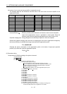
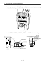
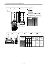
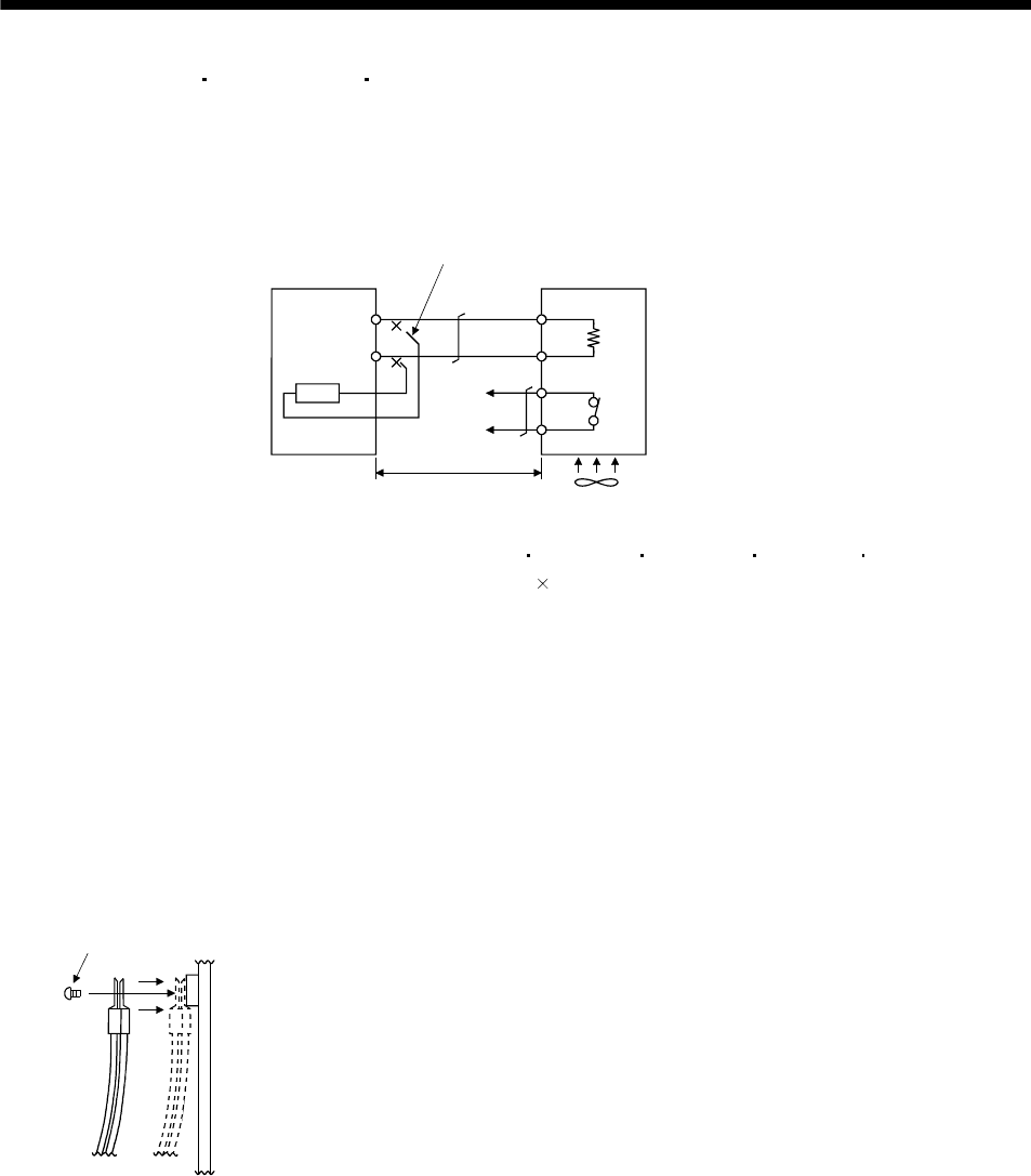
Always remove the wiring (across P-C) of the servo amplifier built-in regenerative resistor and fit the
regenerative option across P-C.
The G3 and G4 terminals act as a thermal sensor. G3-G4 is opened when the regenerative option
overheats abnormally.
Regenerative optionServo amplifier
Cooling fan(Note 1)
P
C
G4
G3
C
P
Always remove wiring (across P-C) of servo
amplifier built-in regenerative resistor.
5m or less
(Note 2)
Note 1. When using the MR-RB51 MR-RB3G-4 MR-RB5G-4 MR-RB34-4 MR-RB54-4, forcibly
cool it with a cooling fan (92
92, minimum air flow : 1.0m
3
).
2. Make up a sequence which will switch off the magnetic contactor (MC) when abnormal heating
occurs.
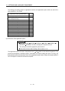
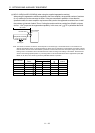
G3-G4 contact specifications
Maximum voltage: 120V AC/DC
Maximum current: 0.5A/4.8VDC
Maximum capacity: 2.4VA
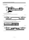
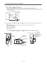
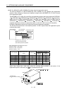
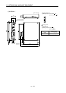
When using the regenerative resistor option, remove the servo amplifier's built-in regenerative resistor
terminals (across P-C), fit them back to back, and secure them to the frame with the accessory screw as
shown below.
Mounting method
Accessory screw