


1 - 5
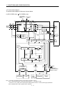
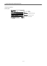
1. FUNCTIONS AND CONFIGURATION
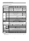
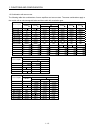
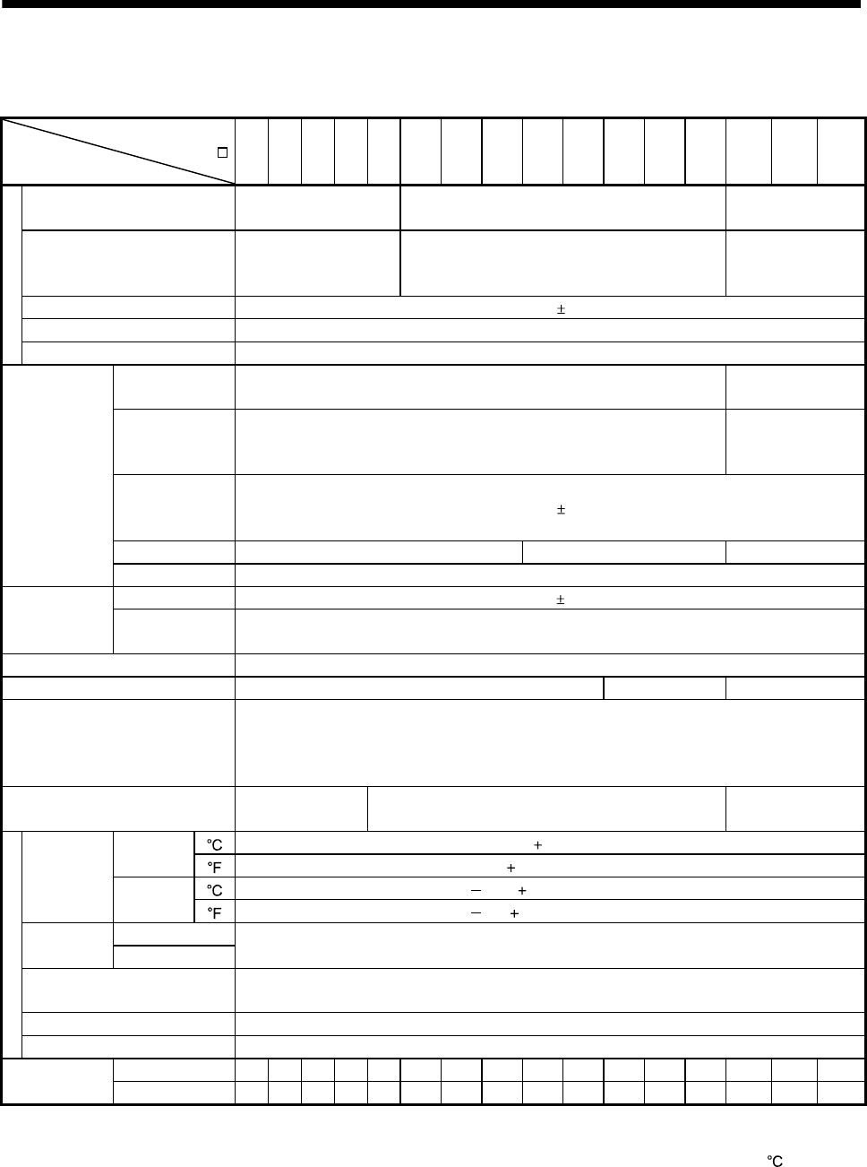
1.3 Servo amplifier standard specifications
(1) 200V class, 100V class
Servo amplifier
MR-J3-
Item
10B 20B 40B 60B 70B 100B 200B 350B 500B 700B 11KB 15KB 22KB 10B1 20B1 40B1
Voltage/frequency
3-phase or 1-phase 200
to 230VAC, 50/60Hz
3-phase 200 to 230VAC, 50/60Hz
1-phase 100V to
120VAC, 50/60Hz
Permissible voltage fluctuation
3-phase or 1-phase 200
to 230VAC: 170 to
253VAC
3-phase 170 to 253VAC
1-phase 85 to
132VAC
Permissible frequency fluctuation Within 5%
Power supply capacity Refer to section 10.2
Power suppl
y
Inrush current Refer to section 10.5
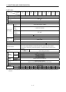
Voltage,
frequency
1-phase 200 to 230VAC, 50/60Hz
1-phase 100 to
120VAC, 50/60Hz
Permissible
voltage
fluctuation
1-phase 170 to 253VAC
1-phase 85 to
132VAC
Permissible
frequency
fluctuation
Within
5%
Input 30W 45W 30W
Control circuit
power supply
Inrush current Refer to section 10.5
Voltage 24VDC 10%
Interface power
supply
Power supply
capacity
(Note 1) 150mA or more
Control System Sine-wave PWM control, current control system
Dynamic brake Built-in External option Built-in
Protective functions
Overcurrent shut-off, regenerative overvoltage shut-off, overload shut-off (electronic thermal relay),
servo motor overheat protection, encoder error protection, regenerative error protection,
undervoltage, instantaneous power failure protection, overspeed protection, excessive error
protection.
Structure
Self-cooled, open
(IP00)
Force-cooling, open (IP00)
Self-cooled, open
(IP00)
[ ] (Note 2) 0 to 55 (non-freezing) In
operation
[
] 32 to 131 (non-freezing)
[ ] 20 to 65 (non-freezing)
Ambient
temperature
In storage
[
] 4 to 149 (non-freezing)
In operation Ambient
humidity
In storage
90%RH or less (non-condensing)
Ambient
Indoors (no direct sunlight)
Free from corrosive gas, flammable gas, oil mist, dust and dirt
Altitude Max. 1000m above sea level
Environmen
t
Vibration 5.9 [m/s
2
] or less
[kg] 0.8 0.8 1.0 1.0 1.4 1.4 2.1 2.3 4.6 6.2 18 18 19 0.8 0.8 1.0
Mass
[lb] 1.76 1.76 2.21 2.21 3.09 3.09 4.63 5.07 10.1 13.7 39.7 39.7 41.9 1.76 1.76 2.21
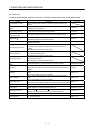
Note 1. 150mA is the value applicable when all I/O signals are used. The current capacity can be decreased by reducing the number of
I/O points.
2. When closely mounting the servo amplifier of 3.5kW or less, operate them at the ambient temperatures of 0 to 45
or at 75% or
smaller effective load ratio.