


13 - 83
13. SERVO AMPLIFIERS WITH A LARGE CAPACITY (30k TO 55kW)
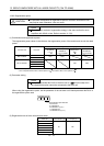
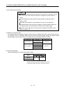
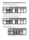
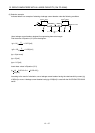
(1) When using the 600V Polyvinyl chloride insulated wire (IV wire)
Selection example of wire size when using IV wires is indicated below.
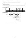
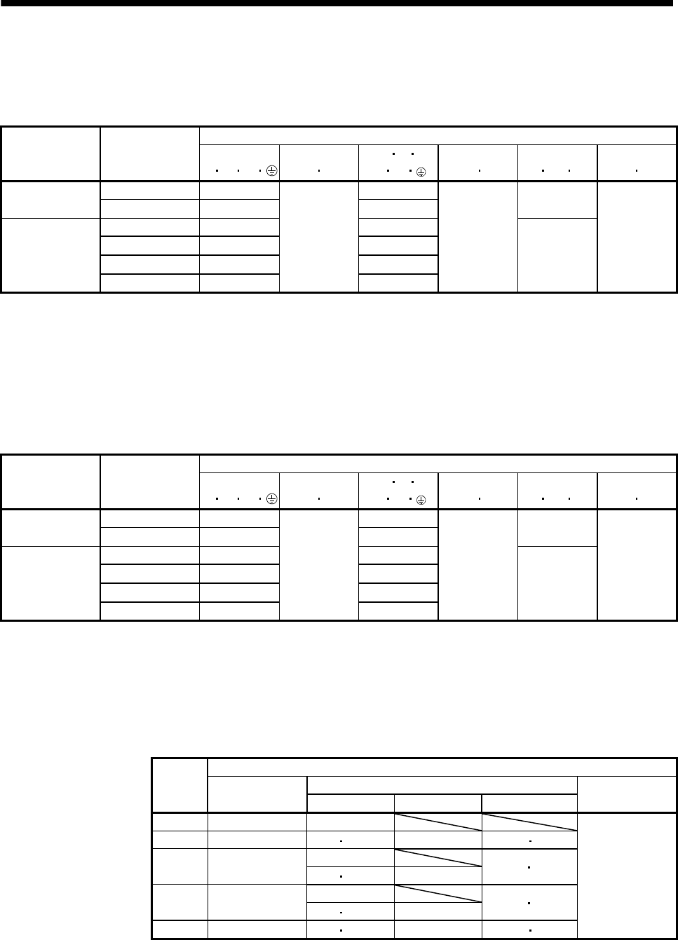
Table 13.4 Wire size selection example 1 (IV wire)
Wires[mm
2
] (Note 1, 3)
Converter unit
(Note 2)
Drive unit
1)
L
1
L
2
L
3
2)
L
11
L
21
3) U
V W
P
1
P
2
4)
P
2
C
5)
BU BV BW
6)
OHS1 OHS2
MR-J3-DU30KB 50(AWG1/0): d 60(AWG2/0): d
MR-J3-CR55K
MR-J3-DU37KB 60(AWG2/0): d (Note 4)
2(AWG14)
MR-J3-DU30KB4 22(AWG4): b 30(AWG2): c
MR-J3-DU37KB4 30(AWG2): c
2(AWG14)
38(AWG2): c
5.5(AWG10): a 1.25(AWG16)
MR-J3-CR55K4
MR-J3-DU45KB4 38(AWG2): c 50(AWG1/0): d
1.25(AWG16)
MR-J3-DU55KB4 50(AWG1/0): d 60(AWG2/0): d
Note 1. Alphabets in the table indicate crimping tools. For crimping terminals and applicable tools, refer to (3) in this section.
2. When connecting to the terminal block, be sure to use the screws which are provided with the terminal block.
3. For the servo motor with a cooling fan.
4. Wires are selected based on the highest rated current among combining servo motors.
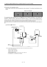
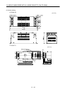
(2) When using the 600V Grade heat-resistant polyvinyl chloride insulated wire (HIV wire)
Selection example of wire size when using HIV wires is indicated below.
Table 13.5 Wire size selection example 2 (HIV wire)
Wires[mm
2
] (Note 1, 3)
Converter unit
(Note 2)
Drive unit
1)
L
1
L
2
L
3
2)
L
11
L
21
3) U
V W
P
1
P
2
4)
P
2
C
5)
BU BV BW
6)
OHS1 OHS2
MR-J3-DU30KB 38(AWG2): c 60(AWG2/0): d
MR-J3-CR55K
MR-J3-DU37KB 60(AWG2/0): d 60(AWG2/0): d
2(AWG14)
MR-J3-DU30KB4 22(AWG4): b 22(AWG4): e
MR-J3-DU37KB4 22(AWG4): b
2(AWG14)
22(AWG4): e
5.5(AWG10): a 1.25(AWG16)
MR-J3-CR55K4
MR-J3-DU45KB4 38(AWG2): c 38(AWG2): c
1.25(AWG16)
MR-J3-DU55KB4 38(AWG2): c 38(AWG2): c
Note 1. Alphabets in the table indicate crimping tools. For crimping terminals and applicable tools, refer to (3) in this section.
2. When connecting to the terminal block, be sure to use the screws which are provided with the terminal block.
3. For the servo motor with a cooling fan.
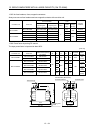
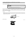
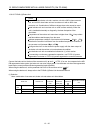
(3) Selection example of crimping terminals
The table below shows a selection example of crimping terminals for the servo amplifier terminal block
when using the wires mentioned in (1) and (2) in this section.
Servo amplifier side crimping terminals
Applicable tool
Symbol
(Note 2)
Crimping terminal
Body Head Dice
Manufacturer
a FVD5.5-10 YNT-1210S
b FVD22-10 YF-1 E-4 YNE-38 DH-123 DH113
YPT-60-21 (Note 1)
c
R38-8
R38-10
YF-1
E-4 YET-60-1
TD-124
TD112
YPT-60-21 (Note 1)
d
R60-10
YF-1
E-4 YET-60-1
TD-125
TD113
e FVD22-8 YF-1 E-4 YNE-38 DH-123 DH-113
Japan Solderless
Terminal
Note 1. Coat the part of crimping with the insulation tube.
2. Make sure to use recommended crimping terminals or equivalent since some crimping terminals
cannot be installed depending on the size.