


3 - 13
3. SIGNALS AND WIRING
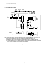
3.3.2 Power-on sequence
(1) Power-on procedure
1) Always wire the power supply as shown in above section 3.1 using the magnetic contactor with the main
circuit power supply (three-phase: L
1
, L
2
, L
3
, single-phase: L
1
, L
2
). Configure up an external sequence
to switch off the magnetic contactor as soon as an alarm occurs.
2) Switch on the control circuit power supply L
11
, L
21
simultaneously with the main circuit power supply or
before switching on the main circuit power supply. If the main circuit power supply is not on, the display
shows the corresponding warning. However, by switching on the main circuit power supply, the warning
disappears and the servo amplifier will operate properly.
3) The servo amplifier can accept the servo-on command within 3s the main circuit power supply is
switched on. (Refer to paragraph (2) of this section.)
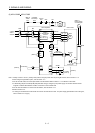
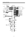
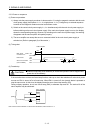
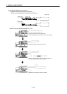
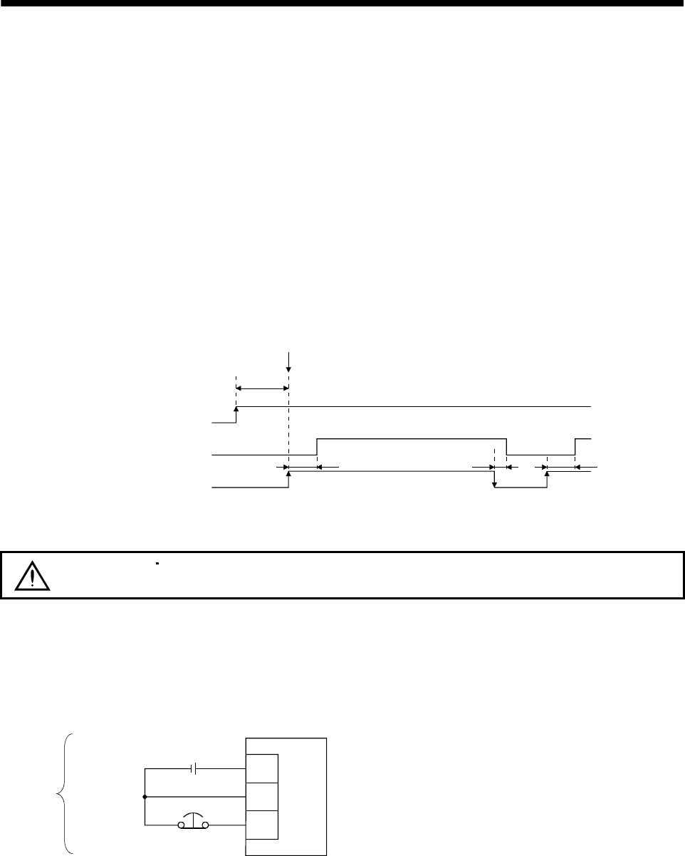
(2) Timing chart
(3s)
ON
OFF
ON
OFF
ON
OFF
10ms 95ms95ms
Base circuit
Servo-on command
(from controller)
SON accepted
Main circuit
Control circuit
power
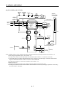
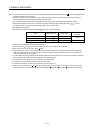
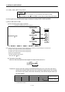
(3) Forced stop
CAUTION
Install an forced stop circuit externally to ensure that operation can be stopped and
power shut off immediately.
If the controller does not have an forced stop function, make up a circuit that switches off main circuit power
as soon as EM1 is turned off at a forced stop. When EM1 is turned off, the dynamic brake is operated to
stop the servo motor. At this time, the display shows the servo forced stop warning (E6).
During ordinary operation, do not use forced stop (EM1) to alternate stop and run. The service life of the
servo amplifier may be shortened.
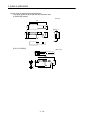
DICOM
DOCOM
EM1
24VDC
Servo amplifier
Forced stop
(Note)
Note. For the sink I/O interface. For the source I/O interface, refer to section 3.7.3.