


13 - 94
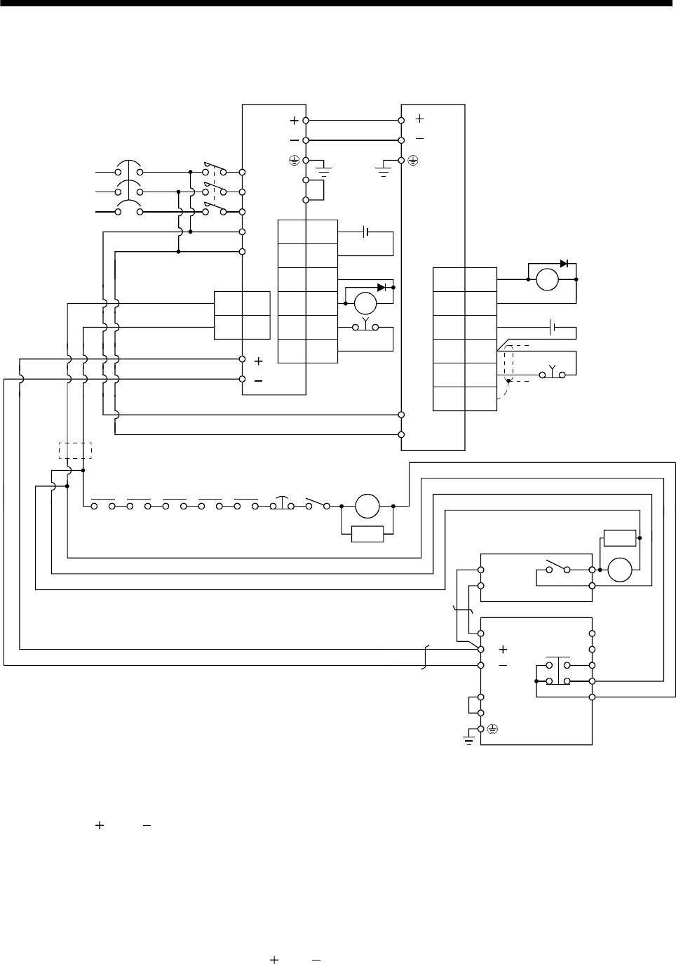
13. SERVO AMPLIFIERS WITH A LARGE CAPACITY (30k TO 55kW)
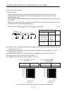
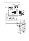
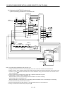
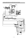
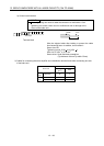
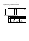
(b) Combination with MT-BR5-(H) resistor unit
1) When connecting a brake unit to a converter unit
NFB
Drive unitConverter unit
L1
L2
L
3
L
11
L
21
(Note 1)
Power supply
L
L
L
L
1MC1
2MC2
CNP1
L
11
L21
RA1
MC
SK
(Note 5)
RA2 RA3
Drive
unit
Converter
unit
Controller
forced stop
(Note 2)
Forced stop
EM1
Operation
ready
OFF/ON
RA4
Servo motor
thermal relay
(Note 8)
RA5
EM1
3
20
SDPlate
DICOM
10
DOCOM
5
DICOM
ALM15
CN3
RA1
Forced stop
(Note 2)
MC
CN1
1
DICOM
5
DOCOM
6
DICOM
2ALM
7EM1
9
DOCOM
(Note 2)
RA2
N/
P/
BUE
SD
PR
B
C
A
SD
MSG
(Note 4)
(Note 7)
RA5
FR-BU2-(H)
MT-BR5-(H)
P
PR
TH2
TH1
(Note 6)
SK
(Note 10)
P
1
P
2
L
L
(Note 9)
(Note 3)
24VDC
24VDC
Note 1. For power supply specifications, refer to section 13.1.3.
2. Configure the circuit to turn OFF the forced stop (EM1) of the drive unit and the converter unit at the same time.
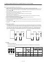
3. Always connect P
1 and P2 terminals (Factory-wired). When using the power factor improving DC reactor, refer to section 13.9.6.
4. Connect P/
and N/ terminals of the brake unit to a correct destination. Wrong connection results in the converter unit and
brake unit malfunction.
5. For the converter unit and the drive unit of 400V class, a stepdown transformer is required.
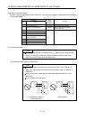
6. Contact rating: 1a contact, 110VAC_5A/220VAC_3A
Normal condition: TH1-TH2 is not conducting. Abnormal condition: TH1-TH2 is conducting.
7. Contact rating: 230VAC_0.3A/30VDC_0.3A
Normal condition: B-C is conducting/A-C is not conducting. Abnormal condition: B-C is not conducting/A-C is conducting.
8. Connect the thermal relay censor of the servo motor.
9. Do not connect more than one cable to each L
and L terminals of TE2-1 of the converter unit.
10. Always connect BUE and SD terminals (Factory-wired).