


13 - 69
13. SERVO AMPLIFIERS WITH A LARGE CAPACITY (30k TO 55kW)
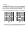
13.8.3 Dynamic brake characteristics
(1) Dynamic brake operation
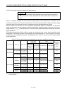
(a) Calculation of coasting distance
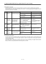
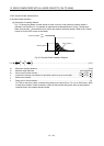
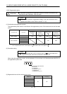
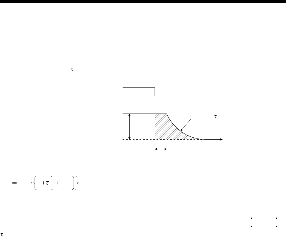
Fig. 13.2 shows the pattern in which the servo motor comes to a stop when the dynamic brake is
operated. Use Equation 13.1 to calculate an approximate coasting distance to a stop. The dynamic
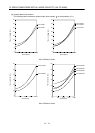
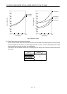
brake time constant
varies with the servo motor and machine operation speeds. (Refer to (b). Please
contact us for the servo motor not indicated.)
t
e
Forced stop (EM1)
Machine speed
Time constant
Time
OFF
ON
V
0
Fig 13.2 Dynamic Brake Operation Diagram
60
L
max
Vo
t
e
1
J
M
J
L
·················································································································· (13.1)
L
max : Maximum coasting distance ·········································································································· [mm]
V
0
: Machine rapid feed rate ······························································································ [mm/min][in/min]
J
M
: Servo motor inertial moment ······················································································ [kg cm
2
][oz in
2
]
J
L
: Load inertia moment converted into equivalent value on servo motor shaft ·············· [kg cm
2
][oz in
2
]
: Brake time constant ·························································································································· [s]
t
e : Delay time of control section ············································································································ [s]
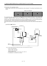
For 7kW or less servo, there is internal relay delay time of about 30ms. For 11k to 22kW servo, there
is delay time of about 100ms caused by a delay of the external relay and a delay of the magnetic
contactor built in the external dynamic brake.