


1
CONTENTS
1. FUNCTIONS AND CONFIGURATION 1 - 1 to 1 -28
1.1 Introduction...............................................................................................................................................1 - 1
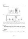
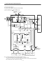
1.2 Function block diagram............................................................................................................................1 - 2
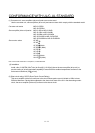
1.3 Servo amplifier standard specifications................................................................................................... 1 - 5
1.4 Function list ..............................................................................................................................................1 - 7
1.5 Model code definition ...............................................................................................................................1 - 8
1.6 Combination with servo motor................................................................................................................1 -10
1.7 Structure ..................................................................................................................................................1 -11
1.7.1 Parts identification ............................................................................................................................1 -11
1.7.2 Removal and reinstallation of the front cover..................................................................................1 -18
1.8 Configuration including auxiliary equipment...........................................................................................1 -21
2. INSTALLATION 2 - 1 to 2 - 6
2.1 Installation direction and clearances .......................................................................................................2 - 1
2.2 Keep out foreign materials.......................................................................................................................2 - 3
2.3 Cable stress .............................................................................................................................................2 - 3
2.4 SSCNET
cable laying............................................................................................................................ 2 - 4
2.5 Inspection items .......................................................................................................................................2 - 6
2.6 Parts having service lives ........................................................................................................................ 2 - 6
3. SIGNALS AND WIRING 3 - 1 to 3 -52
3.1 Input power supply circuit ........................................................................................................................3 - 2
3.2 I/O signal connection example ...............................................................................................................3 -10
3.3 Explanation of power supply system......................................................................................................3 -12
3.3.1 Signal explanations ..........................................................................................................................3 -12
3.3.2 Power-on sequence .........................................................................................................................3 -13
3.3.3 CNP1, CNP2, CNP3 wiring method ................................................................................................3 -14
3.4 Connectors and signal arrangements ....................................................................................................3 -23
3.5 Signal (device) explanations...................................................................................................................3 -24
3.6 Alarm occurrence timing chart................................................................................................................3 -27
3.7 Interfaces.................................................................................................................................................3 -28
3.7.1 Internal connection diagram ............................................................................................................3 -28
3.7.2 Detailed description of interfaces.....................................................................................................3 -29
3.7.3 Source I/O interfaces .......................................................................................................................3 -31
3.8 Treatment of cable shield external conductor ........................................................................................3 -32
3.9 SSCNET
cable connection ..................................................................................................................3 -33
3.10 Connection of servo amplifier and servo motor ...................................................................................3 -35
3.10.1 Connection instructions..................................................................................................................3 -35
3.10.2 Power supply cable wiring diagrams.............................................................................................3 -36
3.11 Servo motor with an electromagnetic brake.........................................................................................3 -46
3.11.1 Safety precautions .........................................................................................................................3 -46
3.11.2 Timing charts..................................................................................................................................3 -47
3.11.3 Wiring diagrams (HF-MP series
HF-KP series servo motor) .....................................................3 -50
3.12 Grounding..............................................................................................................................................3 -51