


11 - 11
11. OPTIONS AND AUXILIARY EQUIPMENT
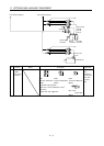
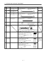
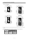
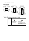
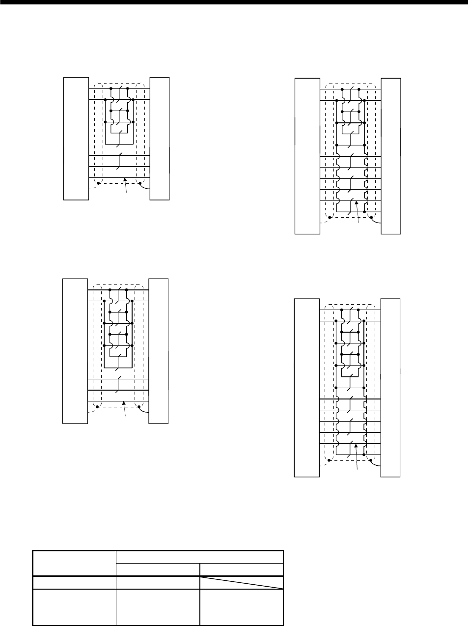
(b) Internal wiring diagram
MR-EKCBL20M-L
Servo amplifier side Encoder side
P5
LG
1
2
MR
MRR
3
4
3
7
9
SD Plate
1
2
8
9
P5G
MR
MRR
SHD
P5E
BATBAT
(Note)
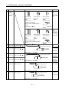
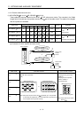
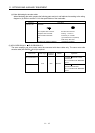
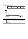
MR-EKCBL30M-L
Servo amplifier side Encoder side
P5
LG
1
2
MR
MRR
3
4
MDR 8 5
3
7
4
MD 7
9
SD
1
2
8
9
P5G
MR
MRR
MDR
MD
SHD
P5E
6CONT
BATBAT
Plate
(Note)
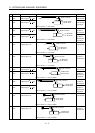
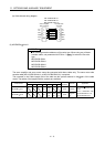
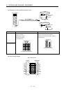
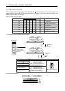
MR-EKCBL20M-H
Servo amplifier side Encoder side
P5
LG
1
2
MR
MRR
3
4
3
7
9
SD
1
2
8
9
P5G
MR
MRR
SHD
P5E
BATBAT
(Note)
Plate
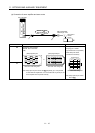
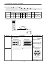
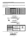
MR-EKCBL30M-H
MR-EKCBL40M-H
MR-EKCBL50M-H
Servo amplifier side Encoder side
P5
LG
1
2
MR
MRR
3
4
MDR 8 5
3
7
4
MD 7
9
SD
1
2
8
9
P5G
MR
MRR
MDR
MD
SHD
P5E
6CONT
BATBAT
(Note)
Plate
Note. Always make connection for use in an absolute position detection system. Wiring is not necessary for use in an incremental
system.
When fabricating the cable, use the wiring diagram corresponding to the length indicated below.
Applicable wiring diagram
Cable flex life
Less than 10m 30m to 50m
Standard MR-EKCBL20M-L
Long flex life MR-EKCBL20M-H MR-EKCBL30M-H
MR-EKCBL40M-H
MR-EKCBL50M-H