


3 - 50
3. SIGNALS AND WIRING
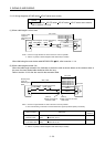
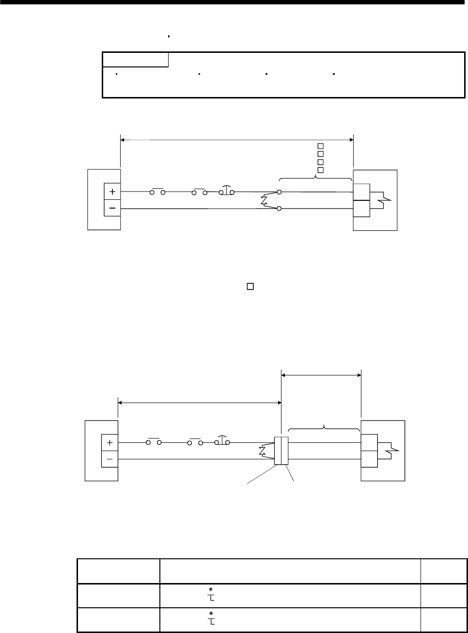
3.11.3 Wiring diagrams (HF-MP series
HF-KP series servo motor)
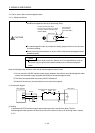
POINT
For HF-SP series HC-RP series HC-UP series HC-LP series servo motors,
refer to section 3.10.2 (2).
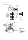
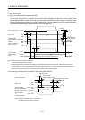
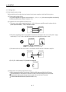
(1) When cable length is 10m or less
AWG20
AWG20
MR-BKS1CBL M-A1-L
MR-BKS1CBL M-A2-L
MR-BKS1CBL M-A1-H
MR-BKS1CBL M-A2-H
(Note 1)
B1
B2
24VDC power
supply for
electromagnetic
brake
Servo motor
10m or less
(Note2)
Electromagnetic
brake (MBR)
Forced stop
(EM1)
Trouble
(ALM)
Note 1. Connect a surge absorber as close to the servo motor as possible.
2. There is no polarity in electromagnetic brake terminals (B1 and B2).
When fabricating the motor brake cable MR-BKS1CBL-
M-H, refer to section 11.1.4.
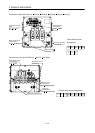
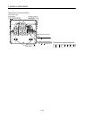
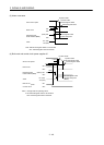
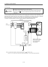
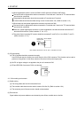
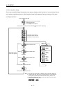
(2) When cable length exceeds 10m
When the cable length exceeds 10m, fabricate an extension cable as shown below on the customer side. In
this case, the motor brake cable should be within 2m long.
Refer to section 11.8 for the wire used for the extension cable.
(Note 2)
a) Relay connector for
extension cable
(Note 2)
b) Relay connector for motor
brake cable
AWG20
AWG20
MR-BKS1CBL2M-A1-L
MR-BKS1CBL2M-A2-L
MR-BKS1CBL2M-A1-H
MR-BKS1CBL2M-A2-H
MR-BKS2CBL03M-A1-L
MR-BKS2CBL03M-A2-L
B1
B2
24VDC power
supply for
electromagnetic
brake
50m or less
Extension cable (To be fabricated)
(Note 1)
2m or less
Servo motor
(Note 3)
Electromagnetic
brake (MBR)
Forced stop
(EM1)
Trouble
(ALM)
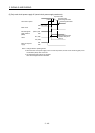
Note 1. Connect a surge absorber as close to the servo motor as possible.
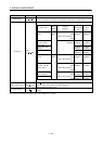
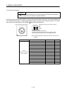
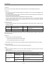
2. Use of the following connectors is recommended when ingress protection (IP65) is necessary.
Relay connector Description
Protective
structure
a) Relay connector for
extension cable
CM10-CR2P-
(DDK)
Wire size: S, M, L
IP65
b) Relay connector for
motor brake cable
CM10-SP2S-
(DDK)
Wire size: S, M, L
IP65
3. There is no polarity in electromagnetic brake terminals (B1 and B2).