


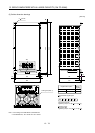
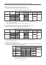
13 - 80
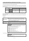
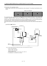
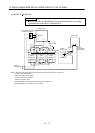
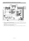
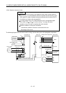
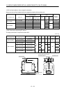
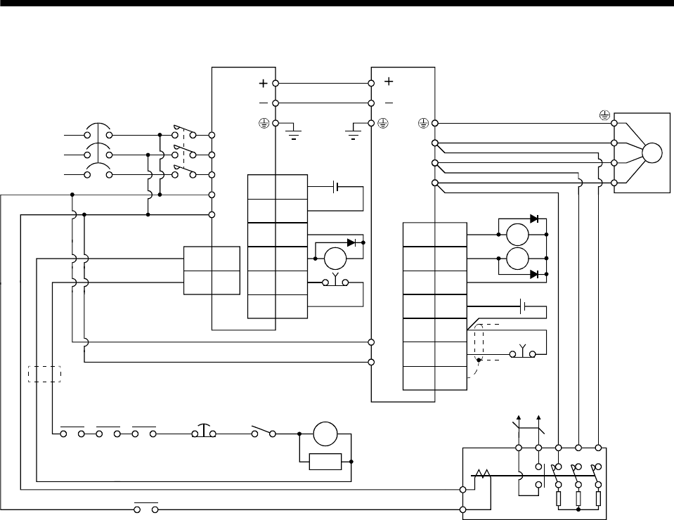
13. SERVO AMPLIFIERS WITH A LARGE CAPACITY (30k TO 55kW)
EM1
(Note 3)
NFB
L1
L
2
L
3
L
11
L
21
U
1MC1
2MC2
CNP1
L11
L21
CN3
RA1
RA4
RA1
MC
SK
(Note 2)
RA2 RA3
CN1
1
DICOM
5
DOCOM
6
DICOM
2ALM
7EM1
9
DOCOM
MC
Forced stop
(Note 5)
L
1
L
2
L
3
L
11
L
21
U
V
W
U
V
W
M
Servo motor
(Note 4)
Power
supply
Drive unitConverter unit
a
b
13 W14 V U
Dynamic brake
(Note 1)
EM1
3
20
SDPlate
DICOM
10
DB
(Note 3)
DOCOM
5
DICOM
ALM15
L
L
L
L
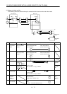
Converter
unit
Controller
forced stop
Operation
-ready
Drive
unit
OFF/ON
(Note 5)
Forced stop
RA4
RA2
Note 1 Terminals 13, 14 are N/O contact outputs. When the dynamic brake has stuck, terminals 13, 14 are opened. Therefore, configure
up the circuit to prevent servo-on in the external sequence.
2. For converter unit and servo amplifier 400 V class, stepdown transformer is required for coil voltage of magnetic contactor more
than 200 V class.
3. Assign the dynamic brake interlock (DB) in parameter No.PD07 to PD09.
4. Refer to section 13.1.3 for the power supply specifications.
5. Make up a sequence that turns off the drive unit forced stop (EM1) and the converter unit forced stop (EM1) at the same time.