


A - 9
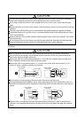
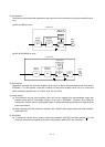
(2) Configuration
The control circuit provide safe separation to the main circuit in the converter unit and servo amplifier (drive
unit).
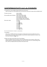
(a) MR-J3-22KB(4) or less
NFB MC
24VDC
power
supply
Servo
amplifier
Reinforced
insulating type
Control box
Servo
motor
No-fuse
breaker
Magnetic
contactor
M
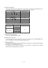
(b) MR-J3-DU30KB(4) or more
NFB MC
24VDC
power
supply
Control box
No-fuse
breaker
Magnetic
contactor
Converter
unit
Servo
motor
M
Drive
unit
Reinforced
insulating type
(3) Environment
Operate the converter unit and servo amplifier (drive unit) at or above the contamination level 2 set forth in
IEC60664-1. For this purpose, install the converter unit and servo amplifier (drive unit) in a control box
which is protected against water, oil, carbon, dust, dirt, etc. (IP54).
(4) Power supply
(a) This converter unit and servo amplifier (drive unit) can be supplied from star-connected supply with
earthed neutral point of overvoltage category III set forth in IEC60664-1. However, when using the
neutral point of 400V class for single-phase supply, a reinforced insulating transformer is required in the
power input section.
(b) When supplying interface power from external, use a 24VDC power supply which has been insulation-
reinforced in I/O.
(5) Grounding
(a) To prevent an electric shock, always connect the protective earth (PE) terminals (marked
) of the
converter unit and servo amplifier (drive unit) to the protective earth (PE) of the control box.