


13 - 49
13. SERVO AMPLIFIERS WITH A LARGE CAPACITY (30k TO 55kW)
13.4 Display section and operation section of the converter unit
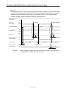
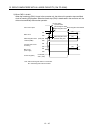
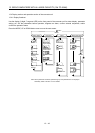
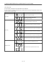
13.4.1 Display flowchart
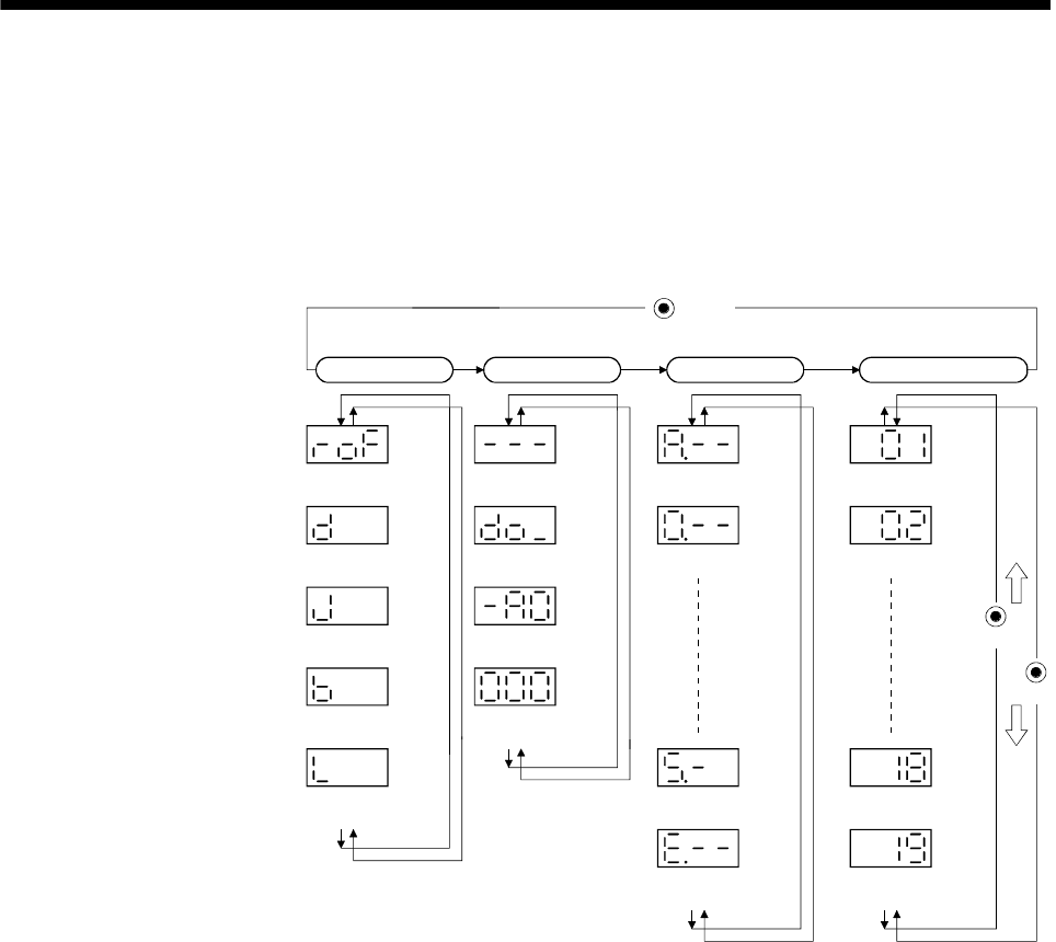
Use the display (3-dight, 7-segment LED) on the front panel of the converter unit for status display, parameter
setting, etc. Set the parameters before operation, diagnose an alarm, confirm external sequences, and/or
confirm the operation status.
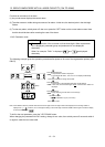
Press the MODE, UP or DOWN button once to move the next screen.
Current alarm
Sixth alarm in
past
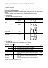
Status display
UP
MODE
Button
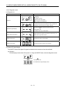
Alarm Basic parameters
Effective load
ratio [%]
Peak load ratio
[%]
Bus voltage
[V]
First alarm in
past
Parameter
No.PA02
Parameter
No.PA01
Parameter error
No.
Parameter
No.PA19
Parameter
No.PA18
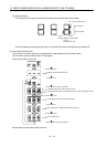
External I/O
signal display
Output signal
forced output
Diagnosis
Software version
high
Software version
low
Regenerative load
ratio [%]
Status
(Note)
(Note)
(Note)
(Note)
DOWN
Note. When parameter is selected, parameter group and parameter No. are displayed
alternately. Refer to section 13.4.5 for details.