


11 - 68
11. OPTIONS AND AUXILIARY EQUIPMENT
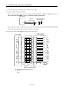
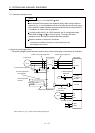
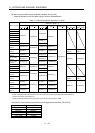
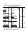
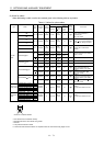
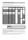
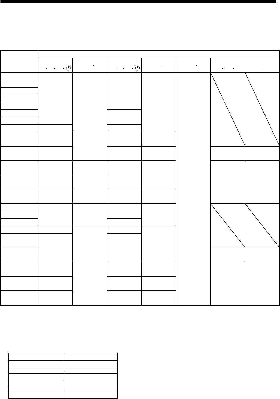
(a) When using the 600V Polyvinyl chloride insulated wire (IV wire)
Selection example of wire size when using IV wires is indicated below.
Table 11.1 Wire size selection example 1 (IV wire)
Wires [mm
2
] (Note 1, 4)
Servo amplifier
1)
L
1 L2 L3
2) L11 L21
3)
U
V W
4) P C 5) B1 B2
6)
BU
BV BW
7)
OHS1 OHS2
MR-J3-10B(1)
MR-J3-20B(1)
MR-J3-40B(1) 1.25(AWG16)
MR-J3-60B 2(AWG14)
MR-J3-70B
1.25(AWG16)
2(AWG14)
MR-J3-100B
MR-J3-200B
2(AWG14)
MR-J3-350B 3.5(AWG12) 3.5(AWG12)
MR-J3-500B
(Note 2)
5.5(AWG10): a 5.5(AWG10): a 2(AWG14): g
MR-J3-700B
(Note 2)
8(AWG8): b
1.25(AWG16):
h
8(AWG8): b 3.5(AWG12): a
2(AWG14)
(Note 3)
1.25(AWG16)
(Note 3)
MR-J3-11KB
(Note 2)
14(AWG6): c 22(AWG4): d
MR-J3-15KB
(Note 2)
22(AWG4): d
1.25(AWG16):
g
30(AWG2): e
5.5(AWG10): j 1.25(AWG16)
2(AWG14) 1.25(AWG16)
MR-J3-22KB
(Note 2)
50(AWG1/0):
f
60(AWG2/0): f 5.5(AWG10): k
MR-J3-60B4
MR-J3-100B4 2(AWG14) 1.25(AWG16)
1.25(AWG16)
2(AWG14)
MR-J3-200B4 2(AWG14)
MR-J3-350B4 2(AWG14): g 2(AWG14): g
MR-J3-500B4
(Note 2)
MR-J3-700B4
(Note 2)
5.5(AWG10): a
1.25(AWG16):
h
5.5(AWG10): a
2(AWG14): g
2(AWG14)
(Note 3)
1.25(AWG16)
(Note 3)
MR-J3-11KB4
(Note 2)
8(AWG8): l 8(AWG8): l 3.5(AWG12): j
MR-J3-15KB4
(Note 2)
14(AWG6): c
1.25(AWG16):
g
22(AWG4): d 5.5(AWG10): j 2(AWG14) 1.25(AWG16)
MR-J3-22KB4
(Note 2)
14(AWG6): m 22(AWG4): n 5.5(AWG10): k
Note 1. Alphabets in the table indicate crimping tools. For crimping terminals and applicable tools, refer to (1) (c) in this section.
2. When connecting to the terminal block, be sure to use the screws which are provided with the terminal block.
3. For the servo motor with a cooling fan.
4. Wires are selected based on the highest rated current among combining servo motors.
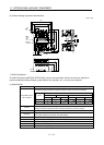
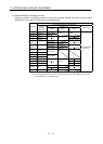
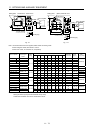
Use wires 8) of the following sizes with the power regeneration converter (FR-RC-(H)).
Model Wires[mm
2
]
FR-RC-15K 14(AWG6)
FR-RC-30K 14(AWG6)
FR-RC-55K 22(AWG4)
FR-RC-H15K 14(AWG6)
FR-RC-H30K 14(AWG6)
FR-RC-H55K 14(AWG6)