


3 - 26
3. SIGNALS AND WIRING
Device Symbol
Connector
pin No.
Function/Application
I/O
division
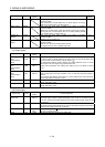
Warning WNG
When using this signal, make it usable by the setting of parameter
No.PD07 to PD09.
When warning has occurred, WNG turns on. When there is no warning,
WNG turns off within about 1.5s after power-on.
DO-1
Battery warning BWNG
When using this signal, make it usable by the setting of parameter
No.PD07 to PD09.
BWNG turns on when battery cable disconnection warning (92) or battery
warning (9F) has occurred. When there is no battery warning, BWNG
turns off within about 1.5s after power-on.
DO-1
Variable gain
selection
CDPS
When using this signal, make it usable by the setting of parameter
No.PD07 to PD09.
CDPS is on during variable gain.
DO-1
Absolute position
erasing
ABSV
When using this signal, make it usable by the setting of parameter
No.PD07 to PD09.
ABSV turns on when the absolute position erased.
This signal cannot be used in position loop mode.
DO-1
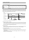
(c) Output signals
Signal name Symbol
Connector
pin No.
Function/Application
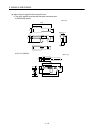
Encoder A-phase
pulse
(Differential line
driver)
LA
LAR
CN3-6
CN3-16
Encoder B-phase
pulse
(Differential line
driver)
LB
LBR
CN3-7
CN3-17
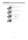
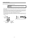
Outputs pulses per servo motor revolution set in parameter No.PA15 in the differential
line driver system. In CCW rotation of the servo motor, the encoder B-phase pulse
lags the encoder A-phase pulse by a phase angle of
/2.
The relationships between rotation direction and phase difference of the A- and B-
phase pulses can be changed using parameter No.PC03.
Output pulse specification and dividing ratio setting can be set. (Refer to section
5.1.9.)
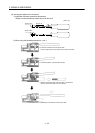
Encoder Z-phase
pulse
(Differential line
driver)
LZ
LZR
CN3-8
CN3-18
Outputs the zero-point signal in the differential line driver system of the encoder. One
pulse is output per servo motor revolution. turns on when the zero-point position is
reached.
The minimum pulse width is about 400
s. For home position return using this pulse,
set the creep speed to 100r/min. or less.
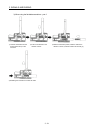
Analog monitor 1 MO1 CN3-4 Used to output the data set in parameter No.PC09 to across MO1-LG in terms of
voltage. Resolution 10 bits
Analog monitor 2 MO2 CN3-14 Used to output the data set in parameter No.PC10 to across MO2-LG in terms of
voltage. Resolution 10 bits
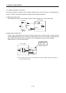
(d) Power supply
Signal name Symbol
Connector
pin No.
Function/Application
Digital I/F power
supply input
DICOM CN3-5
CN3-10
Used to input 24VDC (24VDC 10% 150mA) for I/O interface of the servo amplifier.
The power supply capacity changes depending on the number of I/O interface points
to be used. Connect the positive terminal of the 24VDC external power supply for the
sink interface.
Digital I/F common DOCOM CN3-3 Common terminal for input device such as EM1 of the servo amplifier. Pins are
connected internally. Separated from LG. Connect the positive terminal of the 24VDC
external power supply for the source interface.
Monitor common LG CN3-1
CN3-11
Common terminal of M01 M02
Pins are connected internally.
Shield SD Plate Connect the external conductor of the shield cable.