


3 - 52
3. SIGNALS AND WIRING
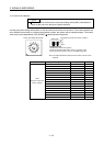
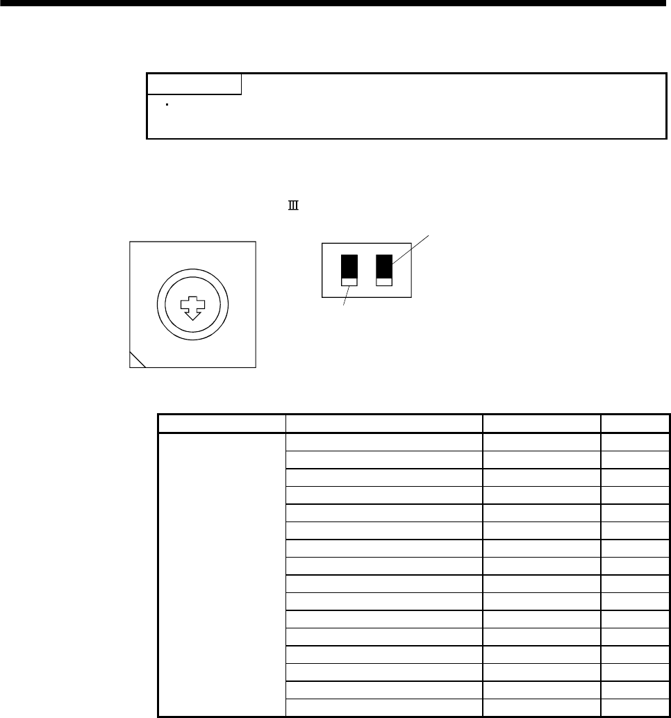
3.13 Control axis selection
POINT
The control axis number set to rotary axis setting switch (SW1) should be the
same as the one set to the servo system controller.
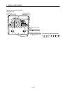
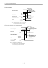
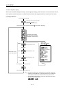
Use the rotary axis setting switch (SW1) to set the control axis number for the servo. If the same numbers are
set to different control axes in a single communication system, the system will not operate properly. The control
axes may be set independently of the SSCNET
cable connection sequence.
8
7
6
5
4
3
2
1
0
F
E
D
C
B
A
9
Rotary axis setting switch (SW1)
Down
Up
Test operation select switch (SW2-1)
Set the test operation select switch to the "Up" position, when
performing the test operation mode by using MR Configurator.
Spare (Be sure to set to the "Down" position.)
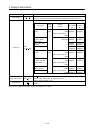
(Note) SW2
Note. This table indicates the status when the switch is set to "Down".
(Default)
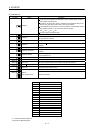
Spare Rotary axis setting switch (SW1) Description Display
0 Axis No.1 01
1 Axis No.2 02
2 Axis No.3 03
3 Axis No.4 04
4 Axis No.5 05
5 Axis No.6 06
6 Axis No.7 07
7 Axis No.8 08
8 Axis No.9 09
9 Axis No.10 10
A Axis No.11 11
B Axis No.12 12
C Axis No.13 13
D Axis No.14 14
E Axis No.15 15
Down
(Be sure to set to the
"Down" position.)
F Axis No.16 16