


3 - 10
3. SIGNALS AND WIRING
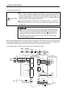
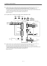
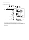
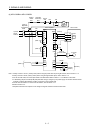
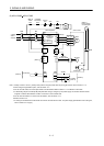
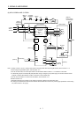
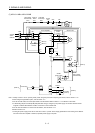
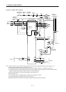
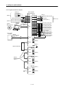
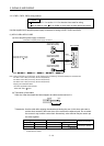
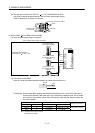
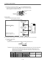
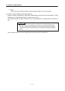
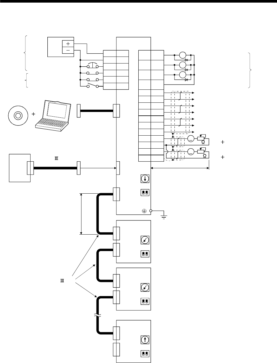
3.2 I/O signal connection example
13
9
15
10
6
16
7
17
2
12
19
CN3
Encoder Z-phase pulse
(differential line driver)
2m Max
(Note 12)
(Note 5)
MR Configurator
Personal
computer
Magnetic brake interlock
CN5
Servo amplifier
CN1A
Servo system
controller
USB cable
MR-J3USBCBL3M
(option)
Trouble (Note 11)
In-position
CN3
(Note 12)
CN1A
CN1B
MR-J3-B
(2 axis)
(Note 7)
(Note 9)
Cap
(Note 1)
CN1B
SW1
21
SW2
SW1
21
SW2
Between electrodes
Control common
(Note 8)
(Note 8)
CN1A
CN1B
MR-J3-B
(Note 7)
SW1
21
SW2
(Note 8)
CN1A
CN1B
MR-J3-B
(Note 7)
SW1
21
SW2
(Note 8)
24VDC
Power
supply
(Note 10)
(Note 3,4)Forced stop
(Note 14)
(3 axis)
(n axis)
(Note 6 )
SSCNET cable
(option)
(Note 6)
SSCNET cable
(option)
Analog monitor 2
Max. 1mA meter
both directions
Analog monitor 1
Max. 1mA meter
both directions
10k
Encoder B-phase pulse
(differential line driver)
Encoder A-phase pulse
(differential line driver)
A
A
10k
(Note 15)
RA3
RA2
RA1
DICOM
DOCOM
EM1
DI1
DI2
DI3
5
3
20
DICOM
MBR
INP
ALM
LA
LAR
LB
LBR
8LZ
18 LZR
11 LG
4MO1
1LG
14 MO2
Plate SD
(Note 2)
(Note 13,14)
Upper stroke limit (FLS)
Lower stroke limit (RLS)
Proximity dog (DOG)