


5 - 19
5. PARAMETERS
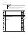
5.3.2 List of details
No. Symbol Name and function
Initial
value
Unit
Setting
range
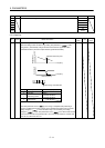
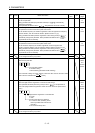
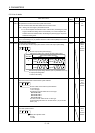
PC01 ERZ
(Note 2)
Error excessive alarm level
This parameter cannot be used in the speed control mode.
Set error excessive alarm level with rotation amount of servo motor.
Note 1. Setting can be changed in parameter No.PC06.
2. For a servo amplifier with software version of B2 or later, reactivating the power
supply to enable the setting value is not necessary. For a servo amplifier with
software version of earlier than B2, reactivating the power supply is required to
enable the setting value.
3 rev
(Note 1)
1
to
200
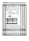
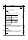
PC02 MBR Electromagnetic brake sequence output
Used to set the delay time (Tb) between electronic brake interlock (MBR) and the base
drive circuit is shut-off.
0 ms 0
to
1000
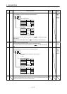
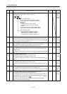
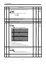
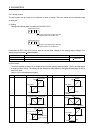
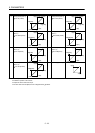
PC03 *ENRS Encoder output pulse selection
Use to select the, encoder output pulse direction and encoder output pulse setting.
CW
Encoder output pulse phase changing
Changes the phases of A, B-phase encoder pulses output .
A-phase
B-phase
CCW
Servo motor rotation direction
Set value
0
1
Encoder output pulse setting selection (refer to parameter No.PA15)
0: Output pulse designation
1: Division ratio setting
00
A-phase
B-phase
A-phase
B-phase
A-phase
B-phase
0000h Refer to
Name
and
function
column.
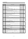
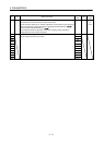
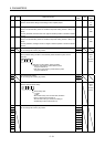
PC04 **COP1 Function selection C-1
Select the encoder cable communication system selection.
00
Encoder cable communication system selection
0: Two-wire type
1: Four-wire type
The following encoder cables are of 4-wire type.
MR-EKCBL30M-L
MR-EKCBL30M-H
MR-EKCBL40M-H
MR-EKCBL50M-H
The other encoder cables are all of 2-wire type.
Incorrect setting will result in an encoder alarm 1 (16) or encoder
alarm 2 (20).
0
0000h Refer to
Name
and
function
column.
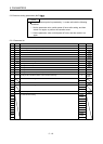
PC05 **COP2 Function selection C-2
Motor-less operation select.
Motor-less operation select.
0: Valid
1: Invalid
000
0000h Refer to
Name
and
function
column.