


11 - 61
11. OPTIONS AND AUXILIARY EQUIPMENT
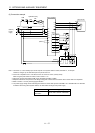
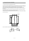
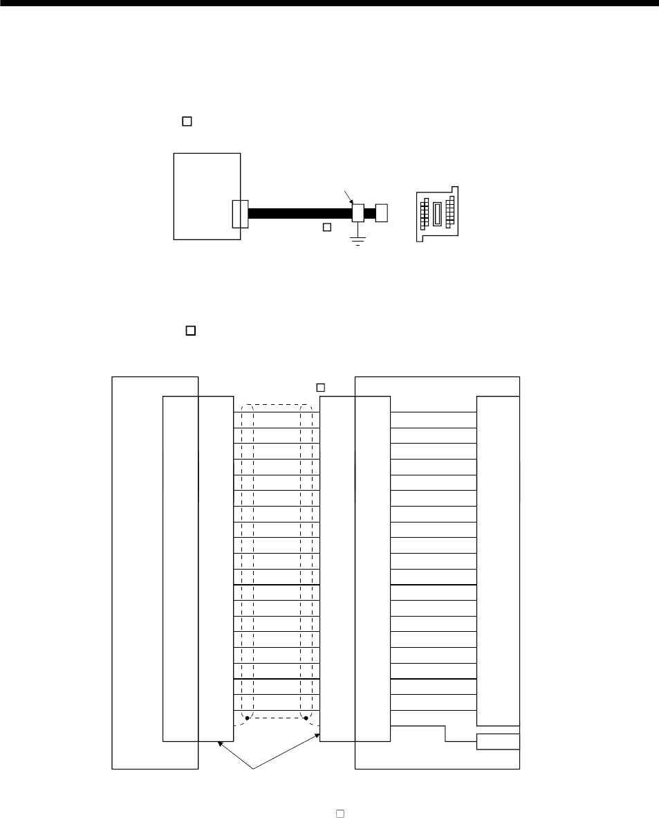
11.7 Junction terminal block PS7DW-20V14B-F (recommended)
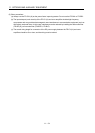
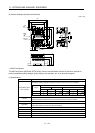
(1) How to use the junction terminal block
Always use the junction terminal block (PS7W-20V14B-F(YOSHIDA ELECTRIC INDUSTRY)) with the
option cable (MR-J2HBUS
M) as a set. A connection example is shown below.
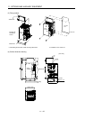
Servo amplifie
r
Cable clamp
(AERSBAN-ESET)
Junction terminal block
PS7DW-20V14B-F
CN3
MR-J2HBUS M
Ground the option cable on the junction terminal block side with the cable clamp fitting (AERSBAN-ESET).
For the use of the cable clamp fitting, refer to section 11.14, (2)(c).
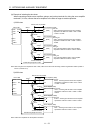
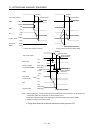
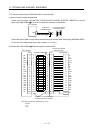
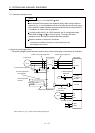
(2) Connection of MR-J2HBUS
M cable and junction terminal block
LG
DI1
1
2
DOC
MO1
3
4
LZ 8
LB 7
9
SD Shell
INP
5
6
10DICO
DICO
LA
LG
DI2
11
12
MBR
MO2
13
14
LZR 18
LBR 17
19DI3
15
16
20EM1
AMR
LAR
Shell Shell Shell
1
2
3
4
8
7
9
5
6
10
11
12
13
14
18
17
19
15
16
20
1
2
3
4
8
7
9
5
6
10
11
12
13
14
18
17
19
15
16
20
1
2
3
4
8
7
9
5
6
10
11
12
13
14
18
17
19
15
16
20
LG
DI1
DOC
MO1
LZ
LB
SD
INP
DICO
DICO
LA
LG
DI2
MBR
MO2
LZR
LBR
DI3
EM1
AMR
LAR
E
Servo amplifier
CN3
Junction terminal block
PS7W-20V14B-F
Connector: 10120-6000EL (3M)
Shell kit: 10320-3210-000 (3M)
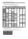
CN
Terminal block
1
2
3
4
8
7
9
5
6
10
11
12
13
14
18
17
19
15
16
20
(Note)MR-J2HBUS M
Note. Symbol indicating cable length is put in .
05: 0.5m
1: 1m
5: 5m