


4 - 3
4. STARTUP
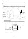
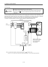
2) When regenerative option is used over 5kW for 200V class and 3.5kW for 400V class
The lead of built-in regenerative resistor connected to P terminal and C terminal of TE1 terminal block
should not be connected.
The generative brake option should be connected to P terminal and C terminal.
A twisted cable should be used when wiring is over 5m and under 10m. (Refer to section 11.2)
3) When brake unit and power regenerative converter are used over 5kW
The lead of built-in regenerative resistor connected to P terminal and C terminal of TE1 terminal block
should not be connected.
Brake unit, power regenerative converter or power regeneration converter should be connected to P
terminal and N terminal. (Refer to section 11.3 to 11.5)
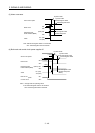
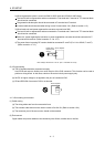
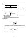
4) The power factor improving DC reactor should be connected P
1 and P2 (For 11k to 22kW, P
1
and P).
(Refer to section 11.13.)
P1
P2
Servo amplifie
r
(Note)
Power factor
improving DC
reactor
Note. Always disconnect P1 and P2. (For 11k to 22kW P1 and P)
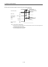
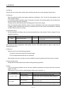
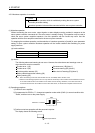
(2) I/O signal wiring
(a) The I/O signals should be connected correctly.
Use DO forced output to forcibly turn on/off the pins of the CN3 connector. This function can be used to
perform a wiring check. In this case, switch on the control circuit power supply only.
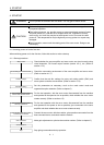
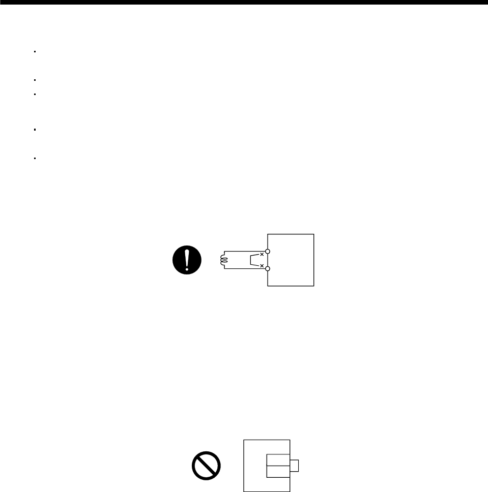
(b) 24VDC or higher voltage is not applied to the pins of connectors CN3.
(c) SD and DOCOM of connector CN3 is not shorted.
DOCOM
SD
CN3
Servo amplifier
4.1.3 Surrounding environment
(1) Cable routing
(a) The wiring cables are free from excessive force.
(b) The encoder cable should not be used in excess of its flex life. (Refer to section 10.4.)
(c) The connector part of the servo motor should not be strained.
(2) Environment
Signal cables and power cables are not shorted by wire offcuts, metallic dust or the like.