


3 - 12
3. SIGNALS AND WIRING
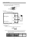
3.3 Explanation of power supply system
3.3.1 Signal explanations
POINT
For the layout of connector and terminal block, refer to outline drawings in
chapter 9.
Abbreviation
Connection target
(Application)
Description
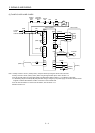
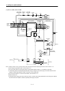
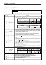
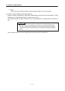
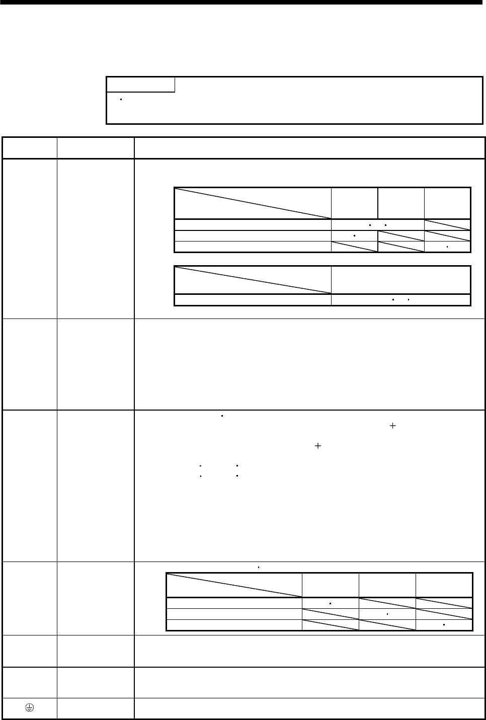
Supply the following power to L1, L2, L3. For the 1-phase 200V to 230VAC power supply, connect
the power supply to L
1, L2, and keep L3 open.
Servo amplifier
Power supply
MR-J3-
10B to 70B
MR-J3-
100B to
22KB
MR-J3-
10B1 to
40B1
3-phase 200V to 230VAC, 50/60Hz L1 L2 L3
1-phase 200V to 230VAC, 50/60Hz L1 L2
1-phase 100V to 120VAC, 50/60Hz L1 L2
Servo amplifier
Power supply
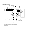
MR-J3-60B4 to 22KB4
3-phase 380V to 480VAC, 50/60Hz L1 L2 L3
L1
L
2
L
3
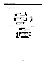
Main circuit power
supply
P1
P
2
Power factor
improving DC
reactor
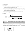
1) MR-J3-700B or less
When not using the power factor improving DC reactor, connect P
1 and P2. (Factory-wired.)
When using the power factor improving DC reactor, disconnect P
1 and P2, and connect the
power factor improving DC reactor to P
1 and P2.
2) MR-J3-11KB(4) to 22KB(4)
MR-J3-11KB(4) to 22KB(4) do not have P
2.
When not using the power factor improving reactor, connect P
1 and P. (Factory-wired)
When using the power factor improving reactor, connect it to P and P
1.
Refer to section 11.13.
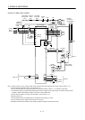
P
C
D
Regenerative
option
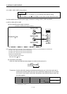
1) MR-J3-350B or less
MR-J3-200B4 or less
When using servo amplifier built-in regenerative resistor, connect P(
) and D. (Factory-
wired)
When using regenerative option, disconnect P(
) and D, and connect regenerative option to
P and C.
2) MR-J3-350B4
500B(4) 700B(4)
MR-J3-350B4
500B(4) 700B(4) do not have D.
When using servo amplifier built-in regenerative resistor, connect P and C. (Factory-wired)
When using regenerative option, disconnect P and C, and connect regenerative option to P
and C.
3) MR-J3-11KB(4) to 22KB(4)
MR-J3-11KB(4) to 22KB(4) do not have D.
When not using the power regenerative converter and the brake unit, make sure to connect
the regenerative option to P and C.
Refer to section 11.2 to 11.5.
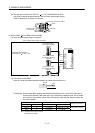
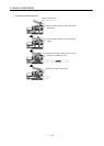
Supply the following power to L11 L21.
Servo amplifier
Power supply
MR-J3-10B to
22KB
MR-J3-10B1 to
40B1
MR-J3-60B4 to
22KB4
1-phase 200V to 230VAC, 50/60Hz L11 L21
1-phase 100V to 120VAC, 50/60Hz L11 L21
1-phase 380V to 480VAC, 50/60Hz L11 L21
L11
L
21
Control circuit
power supply
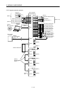
U
V
W
Servo motor power
Connect to the servo motor power supply terminals (U, V, W). During power-on, do not open or
close the motor power line. Otherwise, a malfunction or faulty may occur.
N
Return converter
Brake unit
When using the power regenerative converter/brake unit, connect it to P and N.
Do not connect to servo amplifier MR-J3-350B(4) or less.
For details, refer to section 11.3 to 11.5.
Protective earth
(PE)
Connect to the earth terminal of the servo motor and to the protective earth (PE) of the control
box to perform grounding.