


13 - 28
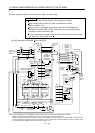
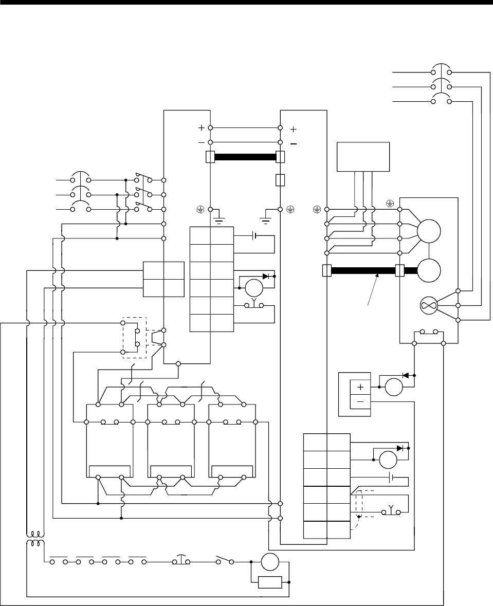
13. SERVO AMPLIFIERS WITH A LARGE CAPACITY (30k TO 55kW)
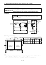
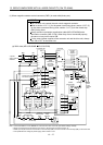
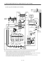
(b) 400V class (MR-J3-DU30KB4 to MR-J3-DU55KB4)
Termination
connector
MR-J3-TM
(Option)
L
L
Encoder cable
Converter unit Drive unit
MC
L
1
L
2
L
3
L11
L
21
NFB
3-phase
380 to 480VAC
50/60Hz
1MC1
2MC2
CN40 CN40A
CN2
Servo motor
thermal relay
RA3
OHS1
BW
BV
BU
M
OHS2
Encoder
V
U
W
CN40B
24VDC
power supply
V
U
W
Servo motor
NFB
(Note 5)
Power
supply
TE2-2
L
L
TE2-1
C
P
1
P
2
Power factor improving
DC reactor (Option)
(Note 2)
L
11
L
21
G4G3
PC
G4G3
PC
S400R400
G4
G3
PC
Regenerative
option(Note 1)
S400R400 S400R400
CNP1
CN1
1
DICOM
5
DOCOM
6
DICOM
RA22ALM
7EM1
9
DOCOM
CN3
EM1
3
20
SDPlate
DICOM
10
ALM15
DOCOM
5
DICOM
RA1
Regenerative
option(Note 1)
Regenerative
option(Note 1)
RA1 RA2 RA3
Converter
unit
Motor
thermal relay
Operation
-ready
Drive
unit
EM1 OFF/ON
SK
RA4
Controller
forced stop
MC
(Note 3)
Forced stop
(Note 3)
(Note 3)
Cooling fan Cooling fan Cooling fan
Cooling fan
(Note 4)
Stepdown
transformer
MR-J3CDL05M
cable
24VDC
Dynamic
brake
(Option)
Dynamic
brake
(Option)
24VDC
Note 1. For the MR-RB138-4. For the MR-RB138-4, three units are used as one set (permissible wattage: 3900W).
2. When using the Power factor improving DC reactor, disconnect the short bar across P
1-P2.
3. Make up a sequence that turns off the drive unit forced stop (EM1) and the converter unit forced stop (EM1) at the same time.
4. Stepdown transformer is required for coil voltage of magnetic contactor more than 200V class.
5. For specifications of cooling fan power supply, refer to section 13.3.8.