


6 - 9
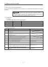
6. GENERAL GAIN ADJUSTMENT
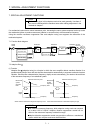
(2) For position control
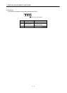
(a) Parameters
The following parameters are used for gain adjustment.
Parameter No. Abbreviation Name
PB06 GD2 Ratio of load inertia moment to servo motor inertia moment
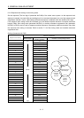
PB07 PG1 Model loop gain
PB08 PG2 Position loop gain
PB09 VG2 Speed loop gain
PB10 VIC Speed integral compensation
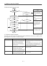
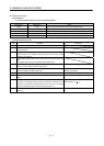
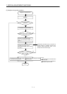
(b) Adjustment procedure
Step Operation Description
1 Brief-adjust with auto tuning. Refer to section 6.2.3.
2 Change the setting of auto tuning to the manual mode (Parameter
No.PA08: 0003).
3 Set an estimated value to the ratio of load inertia moment to servo motor
inertia moment. (If the estimate value with auto tuning is correct, setting
change is not required.)
4 Set a slightly smaller value to the model loop gain and the position loop
gain.
Set a slightly larger value to the speed integral compensation.
5 Increase the speed loop gain within the vibration- and unusual noise-free
range, and return slightly if vibration takes place.
Increase the speed loop gain.
6 Decrease the speed integral compensation within the vibration-free range,
and return slightly if vibration takes place.
Decrease the time constant of the speed
integral compensation.
7 Increase the position loop gain, and return slightly if vibration takes place. Increase the position loop gain.
8 Increase the model loop gain, and return slightly if overshooting takes
place.
Increase the position loop gain.
9 If the gains cannot be increased due to mechanical system resonance or
the like and the desired response cannot be achieved, response may be
increased by suppressing resonance with filter tuning mode or machine
resonance suppression filter and then executing steps 3 to 5.
Suppression of machine resonance.
Refer to section 7.2
7.3.
10 While checking the settling characteristic and rotational status, fine-adjust
each gain.
Fine adjustment