


4 - 6
4. STARTUP
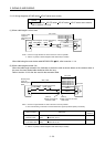
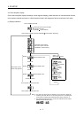
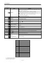
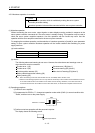
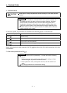
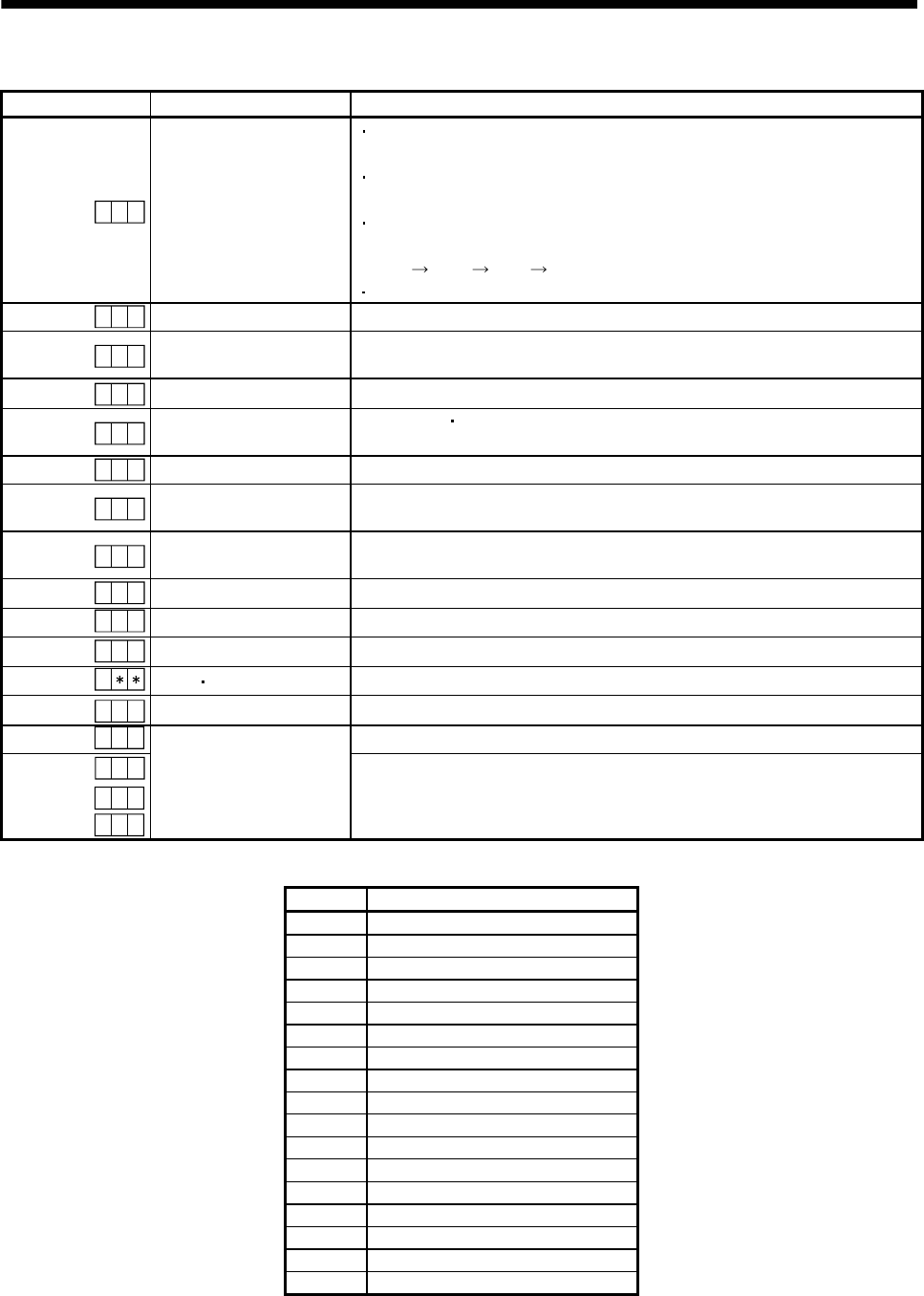
(2) Indication list
Indication Status Description
A b
Initializing
Power of the servo amplifier was switched on at the condition that the power of
servo system controller is OFF.
The axis No. set to the servo system controller does not match the axis No. set
with the rotary axis setting switch (SW1) of the servo amplifier.
A servo amplifier fault occurred or an error took place in communication with the
servo system controller. In this case, the indication changes.
"Ab "
"AC " "Ad " "Ab "
The servo system controller is faulty.
.
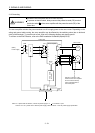
A
b
Initializing During initial setting for communication specifications
A C
Initializing
Initial setting for communication specifications completed, and then it synchronized
with servo system controller.
A d
Initializing During initial parameter setting communication with servo system controller
A E
Initializing
During motor
encoder information and telecommunication with servo system
controller
A F
Initializing During initial signal data communication with servo system controller
A H
Initializing completion
During the completion process for initial data communication with servo system
controller
A A
Initializing standby
The power supply of servo system controller is turned off during the power supply
of servo amplifier is on.
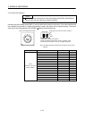
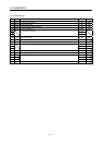
(Note 1)
b # #
Ready OFF The ready off signal from the servo system controller was received.
(Note 1)
d # #
Servo ON The ready off signal from the servo system controller was received.
(Note 1)
C # #
Servo OFF The ready off signal from the servo system controller was received.
(Note 2)
Alarm
Warning The alarm No./warning No. that occurred is displayed. (Refer to section 9.1.)
8 88
CPU Error CPU watchdog error has occurred.
(Note 3)
0 0.b
JOG operation, positioning operation, programmed operation, DO forced output.
(Note 1)
# #.b
# #.d
# #.C
(Note 3)
Test operation mode
Motor-less operation
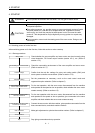
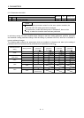
Note 1. ## denotes any of numerals 00 to 16 and what it means is listed below.
# Description
0 Set to the test operation mode.
1 First axis
2 Second axis
3 Third axis
4 Fourth axis
5 Fifth axis
6 Sixth axis
7 Seventh axis
8 Eighth axis
9 Ninth axis
10 Tenth axis
11 Eleventh axis
12 Twelfth axis
13 Thirteenth axis
14 Fourteenth axis
15 Fifteenth axis
16 Sixteenth axis
2. ** indicates the warning/alarm No.
3. Requires the MR Configurator.