


3 - 2
3. SIGNALS AND WIRING
3.1 Input power supply circuit
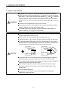
CAUTION
Always connect a magnetic contactor (MC) between the main circuit power supply
and L
1, L2, and L3 of the servo amplifier, and configure the wiring to be able to shut
down the power supply on the side of the servo amplifier’s power supply. If a
magnetic contactor (MC) is not connected, continuous flow of a large current may
cause a fire when the servo amplifier malfunctions.
Use the trouble signal to switch main circuit power supply off. Otherwise, a
regenerative transistor fault or the like may overheat the regenerative resistor,
causing a fire.
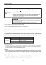
POINT
Even if alarm has occurred, do not switch off the control circuit power supply.
When the control circuit power supply has been switched off, optical module
does not operate, and optical transmission of SSCNET
communication is
interrupted. Therefore, the servo amplifier on the rear axis displays "AA" at
the indicator and turns into base circuit shut-off. The servo amplifier stops
with starting dynamic brake.
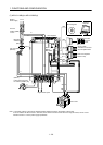
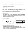
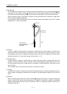
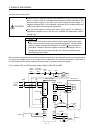
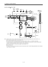
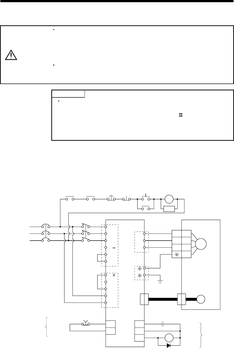
Wire the power supply/main circuit as shown below so that power is shut off and the servo-on command turned
off as soon as an alarm occurs, a servo forced stop is made valid, or a controller forced stop is made valid. A
no-fuse breaker (NFB) must be used with the input cables of the main circuit power supply.
(1) For 3-phase 200V to 230VAC power supply to MR-J3-10B to MR-J3-350B
EM1
NFB MC
L
1
L
2
L3
ALM RA1
P1
P( )
DICOM
DOCOM
L11
L21
N( )
D
C
U
V
W
(Note 1)
(Note 2)
CNP1
CNP3
PE
CNP2
U
V
W
2
3
4
1
M
Motor
Encoder
CN2
24VDC
(Note 3)
Encoder cable
(Note 6)
DOCOM
Forced stop
CN3CN3
OFF
Forced
stop
ON
MC
MC
SK
(Note 4)
Alarm
RA1
Controller
forced stop
RA2
Servo amplifier Servo motor
(Note 5)
Trouble
(Note 4)
(Note 5)
3-phase
200 to
230VAC
P
2