


8 - 4
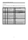
8. TROUBLESHOOTING
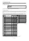
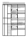
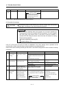
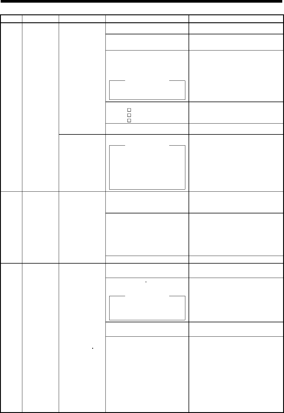
Display Name Definition Cause Action
1. Wrong setting of parameter No.
PA02
Set correctly.
2. Built-in regenerative resistor or
regenerative option is not
connected.
Connect correctly.
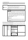
3. High-duty operation or continuous
regenerative operation caused the
permissible regenerative power of
the regenerative option to be
exceeded.
Checking method
Call the status display and check
the regenerative load ratio.
1. Reduce the frequency of positioning.
2. Use the regenerative option of larger
capacity.
3. Reduce the load.
4. Power supply voltage is abnormal.
MR-J3-
B:260VAC or more
MR-J3-
B1:More than 135VAC
MR-J3-
B4: 535VAC or more
Check the power supply.
Permissible
regenerative power
of the built-in
regenerative resistor
or regenerative
option is exceeded.
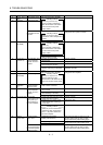
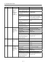
5. Built-in regenerative resistor or
regenerative option faulty.
Change the servo amplifier or regenerative
option.
30 Regenerative
error
Regenerative
transistor fault
6. Regenerative transistor faulty.
Checking method
1) The regenerative option has
overheated abnormally.
2) The alarm occurs even after
removal of the built-in
regenerative resistor or
regenerative option.
Change the servo amplifier.
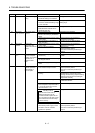
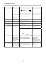
1. Small acceleration/deceleration time
constant caused overshoot to be
large.
Increase acceleration/deceleration time
constant.
2. Servo system is instable to cause
overshoot.
1. Re-set servo gain to proper value.
2. If servo gain cannot be set to proper
value.
1) Reduce load inertia moment ratio; or
2) Reexamine acceleration/
deceleration time constant.
31 Overspeed Speed has exceeded
the instantaneous
permissible speed.
3. Encoder faulty. Change the servo motor.
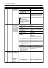
32 Overcurrent 1. Short occurred in servo motor power
(U, V, W).
Correct the wiring.
2. Transistor (IPM IGBT) of the servo
amplifier faulty.
Checking method
Alarm (32) occurs if power is
switched on after U,V and W are
disconnected.
Change the servo amplifier.
3. Ground fault occurred in servo
motor power (U, V, W).
Correct the wiring.
Current that flew is
higher than the
permissible current of
the servo amplifier.
(If the alarm (32)
occurs again when
turning ON the servo
after resetting the
alarm by turning
OFF/ON the power
when the alarm (32)
first occurred, the
transistor (IPM
IGBT) of the servo
amplifier may be at
fault. In the case, do
not repeat to turn
OFF/ON the power.
Check the transistor
with the checking
method of “Cause
2”.)
4. External noise caused the
overcurrent detection circuit to
misoperate.
Take noise suppression measures.