


3 - 38
3. SIGNALS AND WIRING
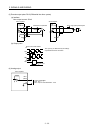
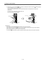
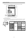
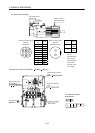
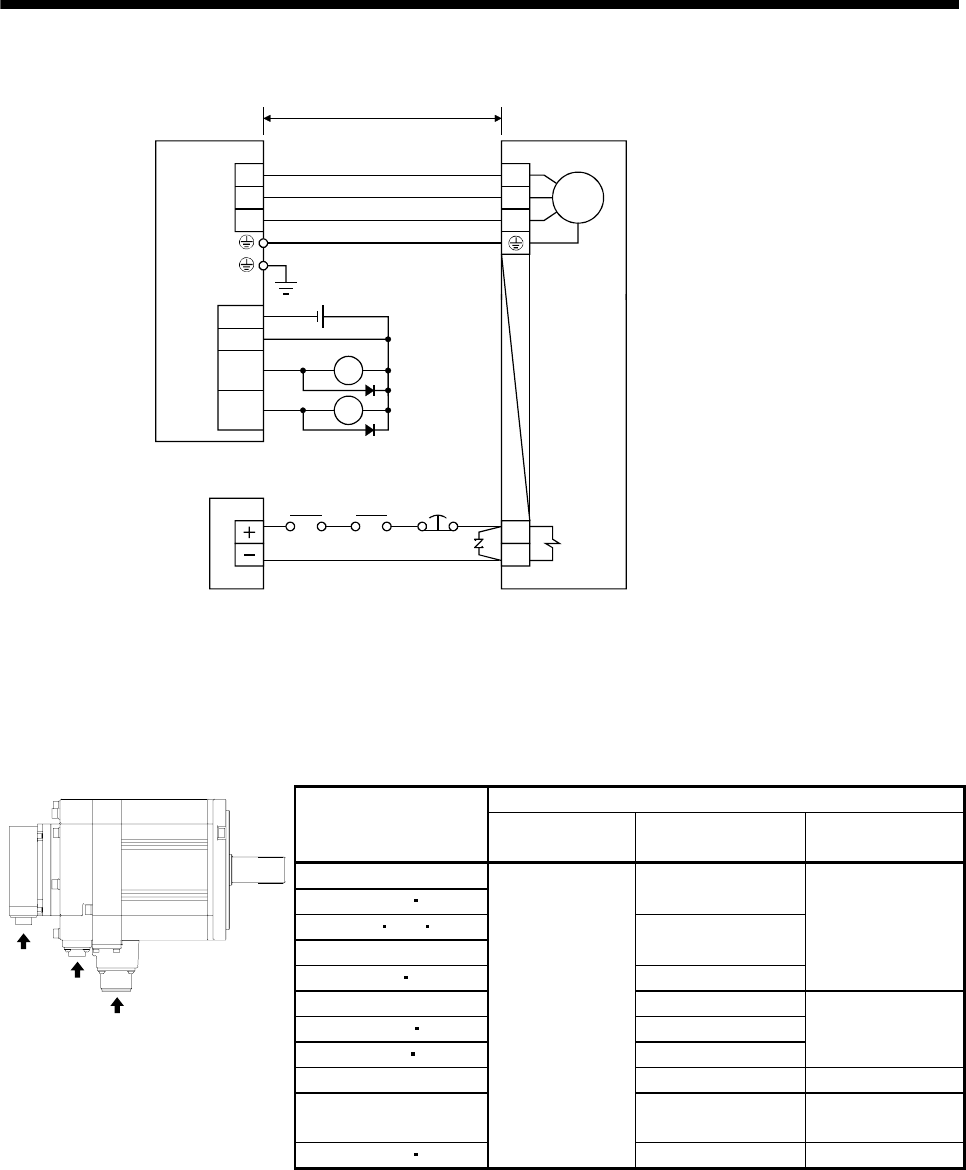
2) When the power supply connector and the electromagnetic brake connector are shared.
Servo motor
(Note)
Servo amplifier
M
U
V
W
B1
B2
U
V
W
24VDC power
supply for
electromagnetic
brake
50m or less
Forced
stop
(EM1)
Trouble
(ALM)
RA1
24VDC
ALM
DOCOM
DICOM
MBR
CN3
RA1
RA2
Electromagnetic
brake interlock
(MBR)
RA2
Note. There is no polarity in electromagnetic brake terminals B1 and B2.
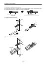
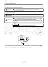
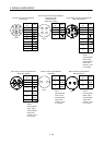
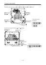
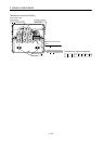
(b) Connector and signal allotment
The connector fitting the servo motor is prepared as optional equipment. Refer to section 11.1. For types
other than those prepared as optional equipment, refer to chapter 3 in Servo Motor Instruction Manual,
Vol. 2 to select.
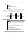
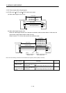
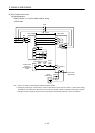
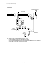
Servo motor side connectors
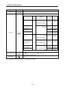
Servo motor
Encoder Power supply
Electromagnetic
brake
HF-SP52(4) to 152(4)
HF-SP51 81
MS3102A18-10P
HF-SP202 352 502(4)
HF-SP121 to 301
MS3102A22-22P
HF-SP421 702(4) CE05-2A32-17PD-B
CM10-R2P
(DDK)
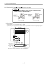
HC-RP103 to 203 CE05-2A22-23PD-B
HC-RP353 503 CE05-2A24-10PD-B
HC-UP72 152 CE05-2A22-23PD-B
The connector for
power is shared
HC-UP202 to 502 CE05-2A24-10PD-B MS3102A10SL-4P
HC-LP52 to 152 CE05-2A22-23PD-B
The connector for
power is shared
a
c
b
HC-LP202 302
CM10-R10P
(DDK)
CE05-2A24-10PD-B MS3102A10SL-4P