


Configuration and Use Manual 87
Operation
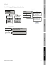
Troubleshooting DisplayDiagramsOperation
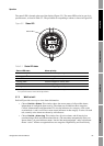
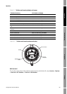
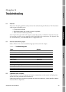
The status LED is located at the top of the display (Figure 5-2). The status LED can be in one of six
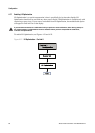
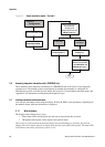
possible states, as listed in Table 5-1. The procedure for responding to alarms is shown in Figure B-5.
Figure 5-2 Status LED
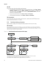
5.7.2 With ProLink II
ProLink II provides two ways to view alarm information:
• Choose
ProLink > Status. This window shows the current status of all possible alarms,
independent of configured alarm severity. The alarms are divided into three categories:
Critical, Informational, and Operational. To view the indicators in a category, click on the
associated tab. A tab is red if one or more status indicators in that category is active. On each
tab, currently active alarms are shown by red indicators.
• Choose
ProLink > Alarm Log. This window lists all active alarms, and all inactive but
unacknowledged Fault and Informational alarms. (The transmitter automatically filters out
Ignore alarms.) A green indicator means “inactive but unacknowledged” and a red indicator
means “active.” Alarms are organized into two categories: High Priority and Low Priority.
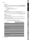
Table 5-1 Status LED states
Status LED state Alarm priority
Green No alarm—normal operating mode
Flashing green
(1)
(1) If the display alarm menu has been disabled, alarms cannot be acknowledged. In this case, the status LED will
never flash to indicate an unacknowledged alarm.
Unacknowledged corrected condition
Yellow Acknowledged low severity alarm
Flashing yellow
(1)
Unacknowledged low severity alarm
Red Acknowledged high severity alarm
Flashing red
(1)
Unacknowledged high severity alarm
Status LED