


86 Model 2700 Transmitter with PROFIBUS-PA
Operation
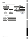
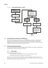
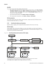
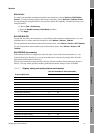
Figure 5-1 Sensor simulation mode – ProLink II
5.6 Accessing diagnostic information with a PROFIBUS host
The transmitter sends diagnostic information to a PROFIBUS host in the form of slave diagnostic
response bytes. The number of bytes sent depends on whether the transmitter is configured for
Manufacturer-specific or Profile-specific mode. See Section 2.5 for information about the mode, and
Appendix E for information on interpreting the diagnostic bytes.
5.7 Viewing transmitter status and alarms
You can view transmitter status using the display, ProLink II, EDD, or bus parameters. Depending on
the method chosen, different information is displayed.
5.7.1 With the display
The display reports alarms in two ways:
• With a status LED, which reports only that one or more alarms has occurred
• Through the alarm queue, which reports each specific alarm
Note: If access to the alarm menu from the display has been disabled (see Section 4.16), then the
display will not list alarm codes in an alarm queue and the status LED will not flash. The status LED
will indicate status using solid green, yellow, or red.
Sensor Simulation tab
Select Enable
Simulation Mode
Apply
ProLink >
Configuration
Select a wave form
for mass flow,
density, and
temperature from the
Wave Form lists
Fixed wave
Triangular or
sine wave
Enter a value in the
Fixed Value box
Enter period in the
Period box
Enter minimum and
maximum amplitude
in the Minimum and
Maximum boxes