


Configuration and Use Manual 9
Startup
Startup ConfigurationCalibrationBefore You Begin
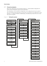
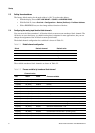
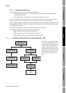
To configure the AI function block channels:
• With the EDD, bus parameters, or ProLink II, see the menu flowcharts in Figure 2-1.
• With the display, see the menu flowchart in Figure B-14.
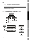
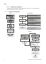
Figure 2-1 Configuring channels and units – EDD, bus parameters, and ProLink II
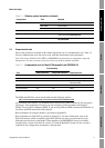
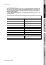
12 (0x0C) 51 (0x33) 0x0C33 Concentration measurement – net volume flow
12 (0x0C) 52 (0x34) 0x0C34 Concentration measurement – concentration
12 (0x0C) 53 (0x35) 0x0C35 Concentration measurement – Baume
Table 2-2 Process variables by transducer block channel (continued)
ProLink II
Function blocks tab
Apply
ProLink >
Configuration
Select a channel for each
AI function block
Select units for each AI
and AO function block
EDD
Bus parameters
Block: Analog Input Block (Slots 1, 2, 3, and 5)
Index: 30 (transducer block channel)
Channel
Block: Analog Input Block (Slots 1, 2, 3, and 5)
Index 28, Parameter 3 (units index)
AI Block units
Block: Analog Output Block (Slots 9 and 10)
Index 27, Parameter 3 (units index)
AO Block
units