


108 Model 2700 Transmitter with PROFIBUS-PA
Troubleshooting
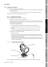
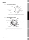
6.13.2 Checking the core processor LED
Do not shut off power to the transmitter when checking the core processor LED. To check the core
processor LED:
1. Expose the core processor according to the instructions in Section 6.13.1.
2. Check the core processor LED against the conditions listed in Table 6-10 (standard core
processor) or Table 6-11 (enhanced core processor).
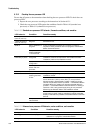
Table 6-10 Standard core processor LED behavior, flowmeter conditions, and remedies
LED behavior Condition Possible remedy
1 flash per second
(75% off, 25% on)
Normal operation No action required
1 flash per second
(25% off, 75% on)
Slug flow See Section 6.10.
Solid on Zero or calibration in
progress
If zero or calibration procedure is in progress, no action is
required. If these procedures are not in progress, contact Micro
Motion Customer Service.
Core processor
receiving between
11.5 and 5 volts
Check power supply to transmitter. See Section 6.9.1.
3 rapid flashes
followed by a pause
Sensor not
recognized
Check wiring between transmitter and sensor (9-wire remote
installation or remote core processor with remote transmitter
installation). Refer to the installation manual.
Improper
configuration
Verify characterization. See Section 3.3.
Broken pin between
sensor and core
processor
Contact Micro Motion Customer Service.
4 flashes per second Fault condition Check alarm status.
OFF Core processor
receiving less than
5volts
Verify power supply wiring to core processor. Refer to the
installation manual.
If status LED is lit, transmitter is receiving power. Check voltage
across terminals 1 (VDC+) and 2 (VDC–) in core processor.
Normal reading is approximately 14 VDC. If reading is normal,
internal core processor failure is possible — contact Micro Motion
Customer Service. If reading is 0, internal transmitter failure is
possible — contact Micro Motion Customer Service. If reading is
less than 1 VDC, verify power supply wiring to core processor.
Wires may be switched. Refer to the installation manual.
If status LED is not lit, transmitter is not receiving power. Check
power supply. If power supply is operational, internal transmitter,
display, or LED failure is possible. Contact Micro Motion Customer
Service.
Core processor
internal failure
Contact Micro Motion Customer Service.
Table 6-11 Enhanced core processor LED behavior, meter conditions, and remedies
LED behavior Condition Possible remedy
Solid green Normal operation No action required.
Flashing yellow Zero in progress If calibration is in progress, no action required. If no
calibration is in progress, contact Micro Motion.
Solid yellow Low severity alarm Check alarm status.