


112 Model 2700 Transmitter with PROFIBUS-PA
Troubleshooting
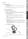
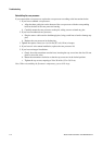
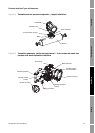
5. If you have a standard core processor, loosen the captive screw (2,5 mm) at the center of the
core processor. Carefully remove the core processor from the sensor by grasping it and lifting
it straight up. Do not twist or rotate the core processor.
6. If you have an enhanced core processor, loosen the two captive screws (2,5 mm) that hold the
core processor in the housing. Gently lift the core processor out of the housing, then
disconnect the sensor cable from the feedthrough pins. Do not damage the feedthrough pins.
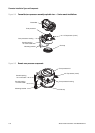
If the core processor (feedthrough) pins are bent, broken, or damaged in any way, the core processor
will not operate. Do not twist or rotate the core processor when lifting it. When replacing the core
processor (or sensor cable) on the pins, be sure to align the guide pins and mount the core processor
(or sensor cable) carefully.
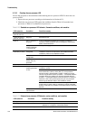
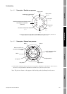
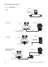
7. Use a digital multimeter (DMM) to check the resistance across the right and left pickoff coils.
See Figure 6-2. Neither pair should be an open circuit (i.e., infinite resistance). The resistance
values should be the same or very close (±5 ohms).
8. Use the DMM to check the resistance across the RTD and LLC (lead length compensation)
circuits. See Figure 6-2. Neither pair should be an open circuit (i.e., infinite resistance).
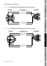
9. Test for a ground to case by checking the resistance between each pin and the sensor case.
With the DMM set to its highest range, there should be infinite resistance on each lead. If there
is any resistance at all, there is a short to case.
If a short to case is indicated, check for moisture or corrosion. If you are unable to determine
the source of the problem, contact Micro Motion Customer Service.
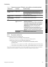
10. Test for shorts across terminals by testing resistance across the following terminal pairs (see
Figures 6-2 and 6-3). There should be infinite resistance in each case. If there is any resistance
at all, there is a short between the terminals.
• Brown against all other terminals except Red
• Red against all other terminals except Brown
• Green against all other terminals except White
• White against all other terminals except Green
• Blue against all other terminals except Gray
• Gray against all other terminals except Blue
• Orange against all other terminals except Yellow and Violet
• Yellow against all other terminals except Orange and Violet
• Violet against all other terminals except Yellow and Orange
Note: D600 sensors and CMF400 sensors with booster amplifiers have different terminal pairs.
Contact Micro Motion Customer Service for assistance.
If a short between terminals is indicated, contact Micro Motion Customer Service.