


Configuration and Use Manual 119
Flowmeter Installation Types and Components
Troubleshooting DisplayDiagramsOperation
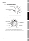
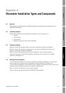
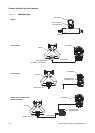
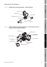
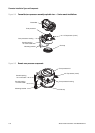
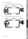
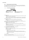
Figure A-6 4-wire cable between Model 2700 transmitter and standard core processor
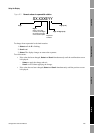
Figure A-7 4-wire cable between Model 2700 transmitter and enhanced core processor
Mating connector
(transmitter)
Core processor
terminals
VDC+ (Red)
VDC– (Black)
RS-485/B (Green)
RS-485/A (White)
User-supplied or
factory-supplied 4-wire cable
Mating connector
(transmitter)
Core processor
terminals
VDC+ (Red)
VDC– (Black)
RS-485/B (Green)
RS-485/A (White)
User-supplied or
factory-supplied 4-wire cable