


Configuration and Use Manual 109
Troubleshooting
Troubleshooting DisplayDiagramsOperation
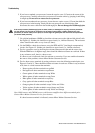
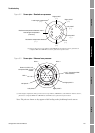
6.13.3 Core processor resistance test
To perform the core processor resistance test:
1. Disconnect power to the transmitter and core processor.
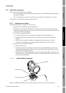
2. Expose the core processor according to the instructions in Section 6.13.1.
3. Measure the resistance across the following terminal pairs:
• The resistance across terminals 3 and 4 (RS-485A and RS-485B) should be
40–50 kilo-ohms.
• The resistance across terminals 2 and 3 (VDC– and RS-485A) should be 20–25 kilo-ohms.
• The resistance across terminals 2 and 4 (VDC– and RS-485B) should be 20–25 kilo-ohms.
If any of the resistance measurements are lower than specified, the core processor may not be able to
communicate with a transmitter or remote host. Contact Micro Motion Customer Service.
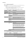
Solid red High severity alarm Check alarm status.
Flashing red (80% on,
20% off)
Tubes not full If alarm A105 (slug flow) is active, see Section 6.10.
If alarm A033 (tubes not full) is active, verify process. Check
for air in the flow tubes, tubes not filled, foreign material in
tubes, or coating in tubes.
Flashing red (50% on,
50% off)
Electronics failed Contact Micro Motion Customer Service.
Flashing red (50% on,
50% off, skips every
4th)
Sensor failed Contact Micro Motion Customer Service.
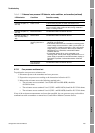
OFF Core processor
receiving less than 5
volts
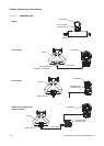
• Verify power supply wiring to core processor
. Refer to
Appendix A for diagrams.
• If transmitter status LED is lit, transmitter is receiving power.
Check voltage across terminals 1 (VDC+) and 2 (VDC–) in
core processor. If reading is less than 1 VDC, verify power
supply wiring to core processor. Wires may be switched.
See Section 6.9.1. Otherwise, contact Micro Motion
Customer Service.
• If transmitter status LED is not lit, transmitter is not
receiving power. Check power supply. See Section 6.9.1. If
power supply is operational, internal transmitter, display, or
LED failure is possible. Contact Micro Motion Customer
Service.
Core processor
internal failure
Contact Micro Motion Customer Service.
Table 6-11 Enhanced core processor LED behavior, meter conditions, and remedies (continued)
LED behavior Condition Possible remedy