


Configuration and Use Manual 73
Configuration
Startup ConfigurationCalibrationBefore You Begin Startup ConfigurationCalibrationBefore You Begin Startup ConfigurationCalibrationBefore You Begin Startup ConfigurationCalibrationBefore You Begin
4.14 Changing the measurement mode parameter
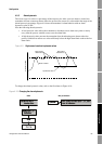
The measurement mode parameter defines how the flow is added to or subtracted from the totalizers.
• Forward flow moves in the direction of the arrow on the sensor.
• Reverse flow moves in the direction opposite from the arrow on the sensor.
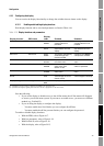
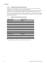
Table 4-15 shows the possible values for the measurement mode parameter and the transmitter’s
behavior when the flow is positive or negative. Only the unidirectional and bidirectional values are
recognized by the PROFIBUS specification, so other values will be unrecognized by a PROFIBUS
host or configuration tool. However, the transmitter will operate correctly in any of the modes listed in
Table 4-15.
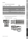
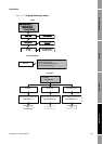
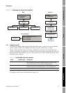
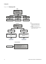
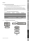
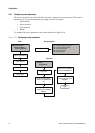
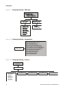
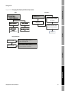
To change the measurement mode parameter, refer to the flowcharts in Figure 4-15.
Figure 4-15 Changing the measurement mode parameter
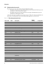
Table 4-15 Totalizer behavior for each measurement mode value
Measurement mode value Bus index Forward flow Reverse flow
Unidirectional (forward only) 0 Increase No change
Reverse only 1 No change Increase
Bidirectional 2 Increase Decrease
Absolute value 3 Increase Increase
Negate/forward only 4 No change Increase
Negate/bidirectional 5 Decrease Increase
MMI Coriolis Flow >
Transducer Block >
Measurement >
Process Variable >
Mass Flow
Measurement Mode
Block: Transducer Block 1 (Slot 11)
Index 10 (measurement mode)
Measurement Mode
EDD Bus parameters
Flow tab
Select a value from
the Flow Direction
list
Apply
ProLink >
Configuration
ProLink II