


Configuration and Use Manual 71
Configuration
Startup ConfigurationCalibrationBefore You Begin Startup ConfigurationCalibrationBefore You Begin Startup ConfigurationCalibrationBefore You Begin Startup ConfigurationCalibrationBefore You Begin
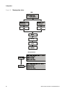
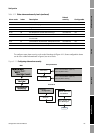
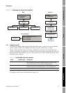
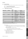
Figure 4-13 Configuring slug flow limits and duration
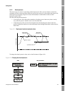
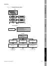
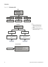
4.13 Configuring cutoffs
Cutoffs are user-defined values below which the transmitter reports a value of zero for the specified
process variable. Cutoffs can be configured for either mass flow, volume flow, or density.
Table 4-14 lists the default values and relevant comments for each cutoff. Note that the mass flow
cutoff is not applied to the volume flow calculation. Even if the mass flow drops below the cutoff, and
therefore the mass flow indicators go to zero, the volume flow rate will be calculated from the actual
mass flow process variable.
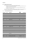
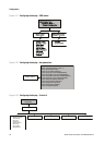
To configure cutoffs, refer to the flowcharts in Figure 4-14.
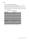
Table 4-14 Cutoff default values and comments
Cutoff Default value Comments
Mass 0.0 g/s Micro Motion recommends a mass flow cutoff value of 0.2% of the
sensor’s maximum flow rate for standard operation, and 2.5% of the
sensor’s maximum flow rate for empty-full-empty batching.
Liquid volume 0.0 L/s The lower limit for volume flow cutoff is 0. The upper limit for volume flow
cutoff is the sensor’s flow calibration factor, in L/s, multiplied by 0.2.
Density 0.2 g/cm
3
The range for density cutoff is 0.0–0.5 g/cm
3
Block: Transducer Block 1 (Slot 11)
Index 130 (duration)
Index 131 (low limit)
Index 132 (high limit)
Slug flow
Density tab
Set the density limits:
• Slug Low Limit
• Slug High Limit
Apply
ProLink >
Configuration
Set the slug flow duration in
the Slug Duration box
Bus parameters
EDD ProLink II
MMI Coriolis Flow >
Transducer Block
Calibration
Slug Limit
Slug Duration Slug Low Limit Slug High Limit