


Configuration and Use Manual 113
Troubleshooting
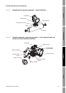
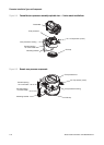
Troubleshooting DisplayDiagramsOperation
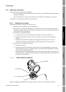
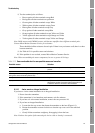
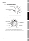
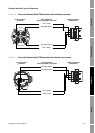
Figure 6-2 Sensor pins – Standard core processor
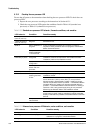
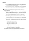
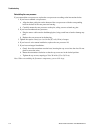
Figure 6-3 Sensor pins – Enhanced core processor
Left pickoff
( + )
Right pickoff
( + )
Drive
( + )
Drive
( – )
Right pickoff
( – )
Left pickoff
( – )
Lead length compensator
(1)
( + )
Resistance temperature detector return /
Lead length compensator
(common)
Resistance temperature detector
( + )
(1) LLC for all sensors except T-Series and CMF400 I.S. For T-Series sensors, functions as
composite RTD. For CMF400 I.S. sensors, functions as fixed resistor.
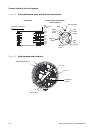
Left pickoff –
Right pickoff –
Drive – Drive +
Right pickoff +
Left pickoff +
Return for RTD, LLC,
composite RTD, or fixed
resistor
RTD +
LLC / Composite RTD /
Fixed resistor
(1)
(1) Lead length compensator (LLC) for all sensors except T-Series, CMF400 I.S., and F300. For T-Series sensors,
functions as composite RTD. For CMF400 I.S. and F300 sensors, functions as fixed resistor.
Note: The pins are shown as they appear while looking at the feedthrough on the sensor.