


Configuration and Use Manual 115
Troubleshooting DisplayDiagramsOperation
Appendix A
Flowmeter Installation Types and Components
A.1 Overview
This appendix provides illustrations of different flowmeter installations and components for the
Model 2700 transmitter.
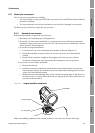
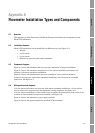
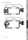
A.2 Installation diagrams
Model 2700 transmitters can be installed in four different ways (see Figure A-1):
•Integral
• 4-wire remote
• 9-wire remote
• Remote core processor with remote transmitter
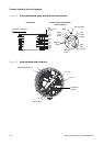
A.3 Component diagrams
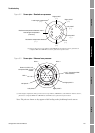
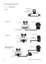
Figure A-2 shows the transmitter and core processor components in integral installations.
Figure A-3 shows the transmitter components in 4-wire remote installations and remote core
processor with remote transmitter installations.
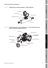
Figure A-4 shows the transmitter/core processor assembly in 9-wire remote installations.
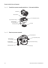
In remote core processor with remote transmitter installations, the core processor is installed
stand-alone. See Figure A-5.
A.4 Wiring and terminal diagrams
In 4-wire remote and remote core processor with remote transmitter installations, a 4-wire cable is
used to connect the core processor to the transmitter’s mating connector. See Figure A-6.
In 9-wire remote installations, a 9-wire cable is used to connect the junction box on the sensor to the
terminals on the transmitter/core processor assembly. See Figure A-8.
Figure A-9 shows the transmitter’s power supply terminals.
Figure A-9 shows the output terminals for the Model 2700 transmitter.