


100 Model 2700 Transmitter with PROFIBUS-PA
Troubleshooting
A010 Calibration failure If alarm appears during zero, ensure there is no flow through the
sensor, then retry.
Cycle power to the flowmeter, then retry.
A011 Calibration too low Ensure there is no flow through sensor, then retry.
Cycle power to the flowmeter, then retry.
A012 Calibration too high Ensure there is no flow through sensor, then retry.
Cycle power to the flowmeter, then retry.
A013 Zero too noisy Remove or reduce sources of electromechanical noise, then attempt
the calibration or zero procedure again.
Possible sources of noise include:
• Mechanical pumps
• Electrical interference
• Vibration effects from nearby machinery
Cycle power to the flowmeter, then retry.
A014 Transmitter failed Cycle power to the transmitter.
The transmitter might need service. Contact Micro Motion Customer
Service.
A016 Line temp out-of-range Check the test points. See Section 6.12.
Check the sensor coils. See Section 6.14.
Check wiring to sensor. See Section 6.9.2.
Verify characterization. Section 6.7.4.
Contact Micro Motion Customer Service.
A017 Meter RTD temperature
out-of-range
Check the test points. See Section 6.12.
Check the sensor coils. See Section 6.14.
Contact Micro Motion Customer Service.
A020 Calibration factors unentered Check the characterization. Specifically, verify the FCF value. See
Section 3.3.
A021 Incorrect sensor type Check the characterization. Specifically, verify the K1 value. See
Section 3.3.
A022 Configuration corrupt The flowmeter needs service. Contact Micro Motion Customer
Service.
A023 Totals corrupt The flowmeter needs service. Contact Micro Motion Customer
Service.
A024 CP program corrupt The flowmeter needs service. Contact Micro Motion Customer
Service.
A025 Boot sector fault Cycle power to the meter.
The flowmeter might need service. Contact Micro Motion Customer
Service.
A026 Sensor/transmitter communication
failure
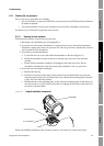
Check wiring between transmitter and core processor (see
Section 6.9.2). The wires may be swapped. After swapping wires,
cycle power to the flowmeter.
Check for noise in wiring or transmitter environment.
Check core processor LED. See Section 6.13.2.
Perform the core processor resistance test. See Section 6.13.3.
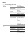
Table 6-4 Status alarms and remedies (continued)
Display
code Description Possible remedies