


Configuration and Use Manual 141
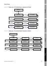
Status Bytes Block ParametersDiagnostic BytesProLink
Appendix E
Slave Diagnostic Response Bytes
E.1 Overview
This appendix describes the diagnostic bytes reported by the transmitter to a PROFIBUS host. There
are two sets of diagnostic bytes sent:
• Bytes 1–6 conform to the standard PROFIBUS specification.
• Byte 7 is the extended diagnostic header byte.
• Bytes 8–15 are extended diagnostic bytes that conform to the Profile 3.01 specification and the
Diagnosis, Alarms, and Timestamping Profile Guidelines.
• The final 10 bytes are extended diagnostic bytes that correspond to alarms in the transmitter.
Alarm codes referenced in these bytes are the codes shown on the transmitter display. Refer to
Section 6.8 for more information about alarm codes.
Note: AI, AO, and totalizer function blocks will go into Out of Service mode when any of the following
diagnostics bits are set: 24 (hardware failure), 28 (memory error), or 29 (measurement failure).
Note: There can be as many as 62 device-related diagnostic bytes.
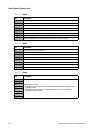
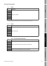
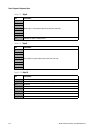
E.2 PROFIBUS specification diagnostic bytes
Tables E-1 through E-6 describe the PROFIBUS diagnostic response bytes.
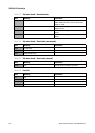
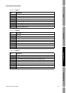
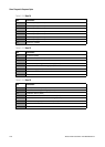
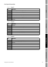
Table E-1 Byte 1
Bit Indication
0 Station not existent (this is set by the master if the slave does not respond)
1 Station not ready for data exchange
2 Configuration fault: slave did not accept last configuration data
3 Slave has extended diagnostic data to report
4 Slave does not support requested parameter function
5 Invalid slave response (this is set by the master)
6 Parameter fault: slave did not accept last parameterization data
7 Slaved is locked or controlled by another master (this is set by the master)