


14 Model 2700 Transmitter with PROFIBUS-PA
Startup
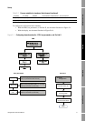
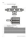
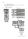
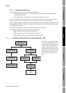
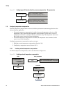
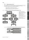
2.7.2 Enabling pressure compensation
To enable pressure compensation, see the menu flowcharts in Figure 2-5. You will need the three
pressure compensation values from Section 2.7.1.
Figure 2-5 Enabling pressure compensation
Block: Transducer Block 1 (Slot 11)
Index 112 (enable pressure compensation)
Enable pressure
comp.
Block: Transducer Block 1 (Slot 11)
Index 116 (flow factor)
Index 117 (density factor)
Index 118 (flow calibration pressure)
Pressure correction
values
Block: Transducer Block 1 (Slot 11)
Index 115 (pressure units)
Pressure units
Block: Transducer Block 1 (Slot 11)
Index 113 (pressure value)
Optional: Fixed
pressure value
View >
Preferences
Select Enable External
Pressure Compensation
Apply
ProLink >
Configuration
Enter values:
Flow factor in Flow factor
box
Density factor in Dens
factor box
Flow calibration pressure in
Cal pressure box
Apply
Pressure tab
Set pressure units to
match source
Optional: Enter a fixed
pressure value in the
External Pressure box
EDD Bus parameters
ProLink II