


Configuration and Use Manual 107
Troubleshooting
Troubleshooting DisplayDiagramsOperation
6.13 Checking the core processor
Two core processor procedures are available:
• You can check the core processor LED. The core processor has an LED that indicates different
flowmeter conditions.
• You can perform the core processor resistance test to check for a damaged core processor.
For both tests you will need to expose the core processor.
6.13.1 Exposing the core processor
Follow these procedures to expose the core processor.
1. Determine your installation type. See Appendix A.
2. If you have a 4-wire remote installation or a remote core processor with remote transmitter
installation, simply remove the core processor lid. The core processor is intrinsically safe and
can be opened in all environments.
3. If you have an integral installation:
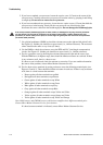
a. Loosen the four cap screws that fasten the transmitter to the base (Figure 6-1).
b. Rotate the transmitter counter-clockwise so that the cap screws are in the unlocked
position.
c. Gently lift the transmitter straight up, disengaging it from the cap screws. Do not
disconnect or damage the wires that connect the transmitter to the core processor.
4. If you have a 9-wire remote installation:
a. Remove the end-cap.
b. Inside the core processor housing, loosen the three screws that hold the core processor
mounting plate in place. Do not remove the screws. Rotate the mounting plate so that the
screws are in the unlocked position.
c. Holding the tab on the mounting plate, slowly lower the mounting plate so that the top of
the core processor is visible. Do not disconnect or damage the wires that connect the core
processor to the transmitter.
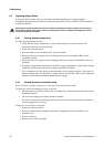
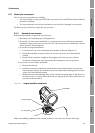
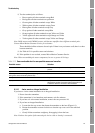
Figure 6-1 Integral installation components
When reassembling components, take care not to pinch or stress the wires. Grease all O-rings.
4 × cap screws
Core processor
Transmitter