


Configuration and Use Manual 43
Calibration
Startup ConfigurationCalibrationBefore You Begin
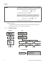
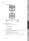
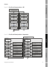
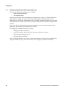
Figure 3-15 D3 or D3-and-D4 density calibration – EDD
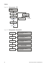
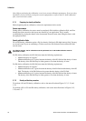
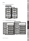
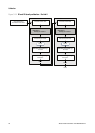
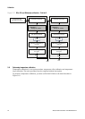
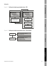
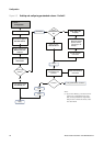
Figure 3-16 D3 or D3-and-D4 density calibration – Bus parameters
D4 calibrationD3 calibration
Calibration >
T-Series Density Cal
Fill sensor with D3
fluid
Start D3 Density Cal
D3 Cal in progress
Execute
Fill sensor with D4
fluid
Start D4 Density Cal
D4 Cal in progress
Execute
Done
Done
D3 = density of D3
fluid
D4 = density of D4
fluid
D4 CalibrationD3 Calibration
Block: Transducer Block 1 (Slot 11)
Index 90 (D3 cal)
Initiate D3 calibration
Fill sensor with D3
fluid
Block: Transducer Block 1 (Slot 11)
Index 95 (K3)
Check K3 value
Block: Transducer Block 1 (Slot 11)
Index 143, Bit 0x0040
Check status
Block: Transducer Block 1 (Slot 11)
Index 141, Bits 0x0100, 0x0200,
and 0x0400
Check for failure
alarms
Block: Transducer Block 1 (Slot 11)
Index 100 (D3)
Enter density of D3
fluid
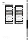
Block: Transducer Block 1 (Slot 11)
Index 91 (D4 cal)
Initiate D4 calibration
Fill sensor with D4
fluid
Block: Transducer Block 1 (Slot 11)
Index 96 (K4)
Check K4 value
Block: Transducer Block 1 (Slot 11)
Index 143, Bit 0x0080
Check status
Block: Transducer Block 1 (Slot 11)
Index 141, Bits 0x0100, 0x0200,
and 0x0400
Check for failure
alarms
Block: Transducer Block 1 (Slot 11)
Index 101 (D4)
Enter density of D4
fluid
Done
Done