


Configuration and Use Manual 151
Status Bytes Block ParametersDiagnostic BytesProLink
Appendix F
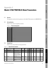
Model 2700 PROFIBUS Block Parameters
F.1 Ove r vi ew
This appendix describes the block parameters of the Model 2700 transmitter with PROFIBUS-PA.
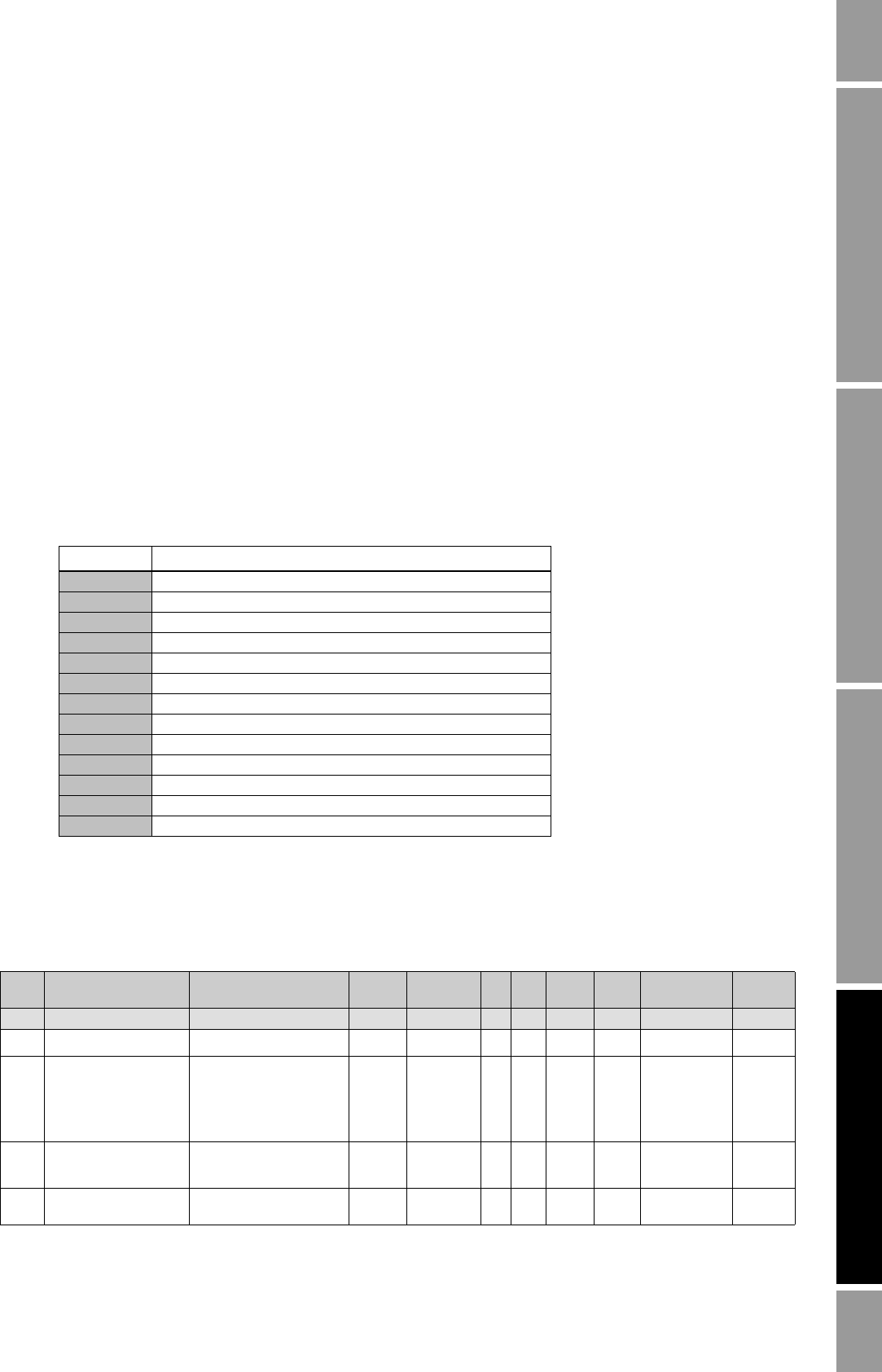
F.2 Slot identification
Table F-1 shows the slot assignment for blocks.
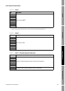
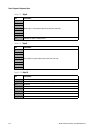
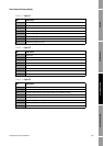
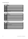
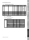
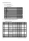
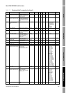
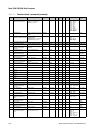
F.3 Physical block
Table F-2 shows the parameters for the physical block.
Table F-1 Block slot assignment
Slot Assigned block
0 Physical block
1 Analog input block 1
2 Analog input block 2
3 Analog input block 3
4 Totalizer block 1
5 Analog input block 4
6 Totalizer block 2
7 Totalizer block 3
8 Totalizer block 4
9 Analog output block 1
10 Analog output block 2
11 Transducer block 1
12 Transducer block 2
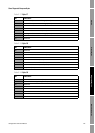
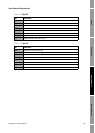
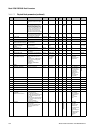
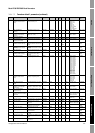
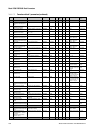
Table F-2 Physical block parameters
Index Parameter Mnemonic Definition Message
Ty pe
Data Type/
Structure
Size Store
/Rate
(HZ)
Default
Value
Access Enumerated List of
Values / Range
Modbus
Register /
Coil
Standard Parameters
16 BLOCK_OBJECT This object contains the
characteristics of the block
RECORD DS-32 20 Cst ---- R NA NA
17 ST_REV A block has static block
parameters that are not changed
by the process. Values are
assigned to this parameter during
the configuration of optimization.
The value of ST_REV increases
by 1 after every change of a static
block parameter.
SIMPLE Unsigned16 2 N 0 R NA NA
18 TAG_DESC Every block can be assigned a
textual TAG description. The
TAG_DESC must be unambiguous
and unique in the field bus system.
SIMPLE Visible
STRING
32 S ‘ ’ R/W NA NA
19 STRATEGY Grouping of function block. The
STRATEGY field can be used to
group blocks.
SIMPLE Unsigned16 2 S 0 R/W NA NA