


C-63
REGISTERS
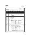
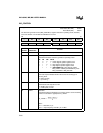
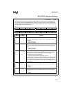
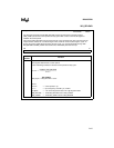
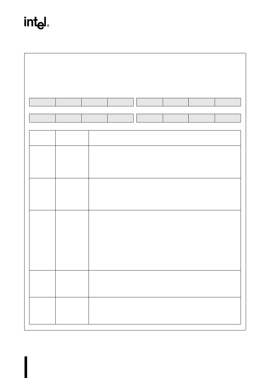
WG_OUTPUT (Waveform Generator)
WG_OUTPUT (Waveform Generator)
Address:
Reset State:
1FC0H
0000H
The waveform generator output configuration (WG_OUTPUT) register controls the configuration of
the waveform generator and PWM module pins. Both the waveform generator and the PWM module
share pins with port 6. Having these control bits in a single register enables you to configure all port 6
pins with a single write to WG_OUTPUT.
15 8
OP1 OP0 SYNC PE7 PE6 PH3.2 PH2.2 PH1.2
7 0
P7 P6 PH3.1 PH3.0 PH2.1 PH2.0 PH1.1 PH1.0
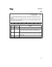
Bit
Number
Bit
Mnemonic
Function
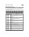
15 OP1 Output Polarity
Selects the output polarity for negative-phase outputs WG1#, WG2#,
and WG3#.
0 = active-low outputs
1 = active-high outputs
14 OP0 Output Polarity
Selects the output polarity for positive-phase outputs WG1, WG2, and
WG3.
0 = active-low outputs
1 = active-high outputs
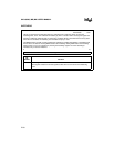
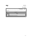
13 SYNC Synchronize
Selects whether updating the WG_OUTPUT register is synchronized
with another event or occurs immediately after you change it.
0 = update WG_OUTPUT immediately
1 = synchronize WG_OUTPUT update with an event
To ensure that the outputs are in the desired states when the waveform
generator starts, you should initially clear this bit, then set it later if you
want subsequent WG_OUTPUT updates to be synchronized with an
event. (Table 9-4 on page C-8 lists the events that update WG_OUTPUT
in each mode.)
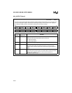
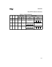
12 PE7 P6.7/PWM1 Function
Selects the port function or the PWM output function of P6.7/PWM1.
0 = P6.7
1 = PWM1
11 PE6 P6.6/PWM0 Function
Selects the port function or the PWM output function of P6.6/PWM0.
0 = P6.6
1 = PWM0