


16-11
PROGRAMMING THE NONVOLATILE MEMORY
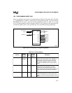
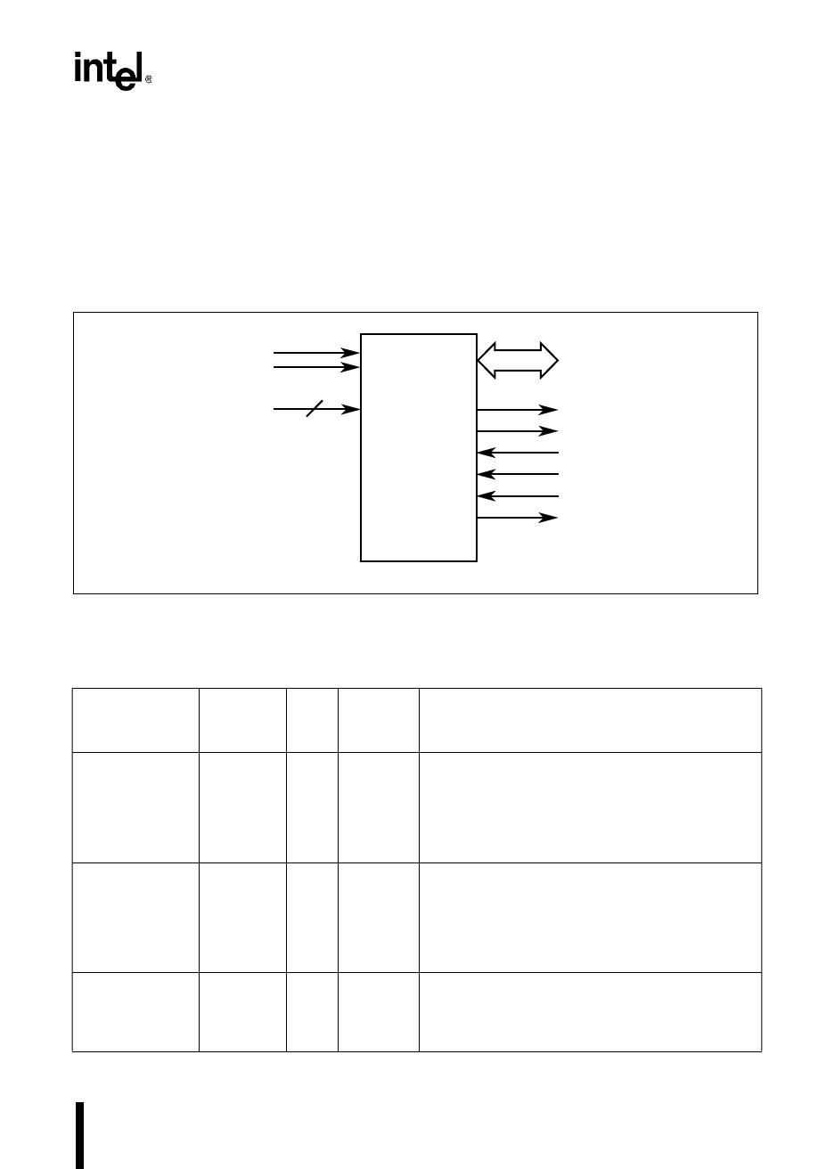
16.6 PROGRAMMING MODE PINS
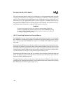
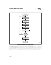
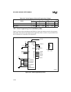
Figure 16-4 illustrates the signals used in programming and Table 16-6 describes them. The EA#,
V
PP
, and PMODE pins combine to control entry into programming modes. You must configure
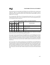
the PMODE (P0.7:4) pins to select the desired programming mode (see Table 16-7 on page
16-13). Each programming routine configures the port 2 pins to operate as the appropriate spe-
cial-function signals. Ports 3 and 4 automatically serve as the PBUS during programming.
Figure 16-4. Pin Functions in Programming Modes
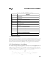
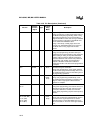
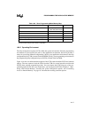
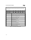
Table 16-6. Pin Descriptions
Port Pin
Special-
function
Signal
Type
Program-
ming
Mode
Description
P0.7:4 PMODE.3:
PMODE.0
I All Programming Mode Select
Determines the programming mode. PMODE is
sampled after a device reset and must be static
while the part is operating. (Table 16-7 on page
16-13 lists the PMODE values and programming
modes.)
P2.0 PVER O Slave
Auto
Programming Verification
During slave or auto programming, PVER is
updated after each programming pulse. A high
output signal indicates successful programming of a
location, while a low signal indicates a detected
error.
P2.1 PALE# I Slave Programming ALE Input
During slave programming, a falling edge causes
the device to read a command and address from the
PBUS.
V
PP
EA#
P2.7
P2.6
P2.4
P2.2
P2.1
P2.0
P4.7:0
P3.7:0
8XC196 Device
PBUS
A2839-02
P0.7:4
PACT#
CPVER
AINC#
PROG#
PALE#
PVER
PMODE.3:0
4
Programming
Voltage