12-13
ANALOG-TO-DIGITAL (A/D) CONVERTER
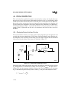
ANGND should be within about ± 50 mV of V
SS
. V
REF
should be well regulated and used only
for the A/D converter. The V
REF
supply can be between 4.5 and 5.5 volts and must be able to
source approximately 5 mA (see the datasheet for actual specifications). V
REF
should be approx-
imately the same voltage as V
CC
. V
REF
and V
CC
should power up at the same time, to avoid poten-
tial latch-up conditions on V
REF
. Large negative current spikes on the ANGND pin relative to V
SS
may cause the analog circuitry to latch up. This is an additional reason to follow careful ground-
ing practice.
The analog reference voltage (V
REF
) is the positive supply to which all A/D conversions are com-
pared. It is also the supply to port 0 (and port 1 for the MC and MD) if the A/D converter is not
being used. If high accuracy is not required, V
REF
can be tied to V
CC
. If accuracy is important,
V
REF
must be very stable. One way to accomplish this is through the use of a precision power sup-
ply or a separate voltage regulator (usually an IC). These devices must be referenced to ANGND,
not to V
SS
, to ensure that V
REF
tracks ANGND and not V
SS
.
12.6.1.4 Using Mixed Analog and Digital Inputs
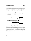
Port 0 (and port 1 for the MC and MD) may be used for both analog and digital input signals at
the same time. However, reading the port may inject some noise into the analog circuitry. For this
reason, make certain that an analog conversion is not in progress when the port is read. Refer to
Chapter 6, “I/O Ports,” for information about using the port as digital inputs.
12.6.2 Understanding A/D Conversion Errors
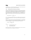
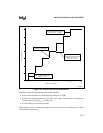
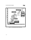
The conversion result is the ratio of the input voltage to the reference voltage.
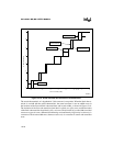
This ratio produces a stair-stepped transfer function when the output code is plotted versus input
voltage. The resulting digital codes can be taken as simple ratiometric information, or they pro-
vide information about absolute voltages or relative voltage changes on the inputs.
The more demanding the application, the more important it is to fully understand the converter’s
operation. For simple applications, knowing the absolute error of the converter is sufficient.
However, closing a servo-loop with analog inputs requires a detailed understanding of an A/D
converter’s operation and errors.
RESULT (8-bit) 255
V
IN
ANGND–
V
REF
ANGND–
-------------------------------------------
×= RESULT (10-bit) 1023
V
IN
ANGND–
V
REF
ANGND–
-------------------------------------------
×=


